Top Design Mistakes to Avoid When Creating Custom Metal Molds?

Even a perfect mold machine can’t fix a bad design.
Design mistakes in custom metal molds lead to casting defects, high rework rates, and failed assembly. Common errors include undercut placement, improper draft angles, poor cooling channel layout, and selecting the wrong material. Fixing them after machining costs 5X more time and budget.
Here’s how to avoid these costly issues before they happen.
Table of Contents
- 1. Ignoring Draft Angles and Wall Thickness Standards
- 2. Undercuts Without a Clear Ejection Strategy
- 3. Inadequate Cooling Channel Placement
- 4. Overlooking Parting Line and Mold Flow
- 5. Selecting the Wrong Metal or Mold Material
- 6. Not Considering Tolerances for Machining or Injection
- 7. Lack of Maintenance Access and Modularity
- FAQs
- Conclusion
1. Ignoring Draft Angles and Wall Thickness Standards
No draft = stuck part. Uneven walls = warping.
Proper draft angles make it easier to eject parts from the mold. Uniform wall thickness ensures balanced cooling and reduces warpage. Draft angles should be 1°–3° minimum, depending on part material and surface finish.
| Feature | Recommendation | Common Mistake |
|---|---|---|
| Draft angle (plastic) | ≥1° | Zero or negative |
| Wall thickness | 1.5–3 mm uniform | Sharp transitions |
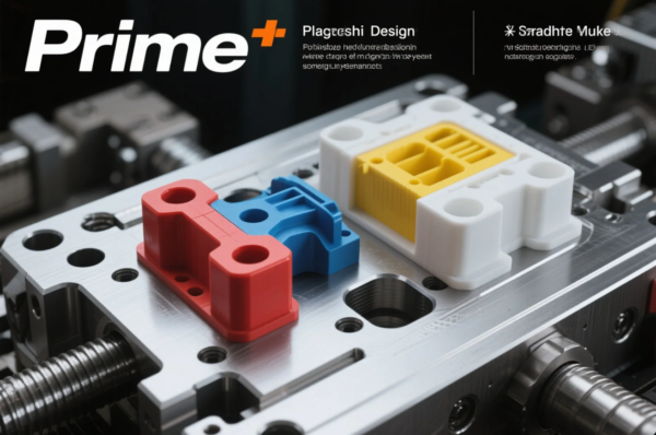
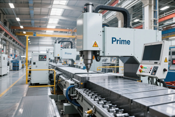
Prime engineers use DFM (Design for Manufacturing) checks to validate every part before mold creation.
2. Undercuts Without a Clear Ejection Strategy
Undercuts look clean in CAD—but can trap parts in real molds.
Undercuts require side actions, lifters, or collapsible cores. Designing them without planning for ejection adds complexity and cost.
| Design Decision | Risk If Ignored | Prime Solution |
|---|---|---|
| Functional undercut | Blocked part removal | Lifters or collapsible core |
| Cosmetic feature | Tool marks or flash | Sliding cavity inserts |
Always ask: “How will this part be ejected safely?”
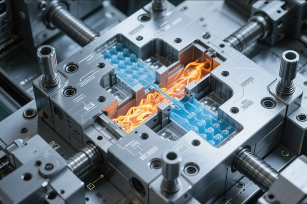
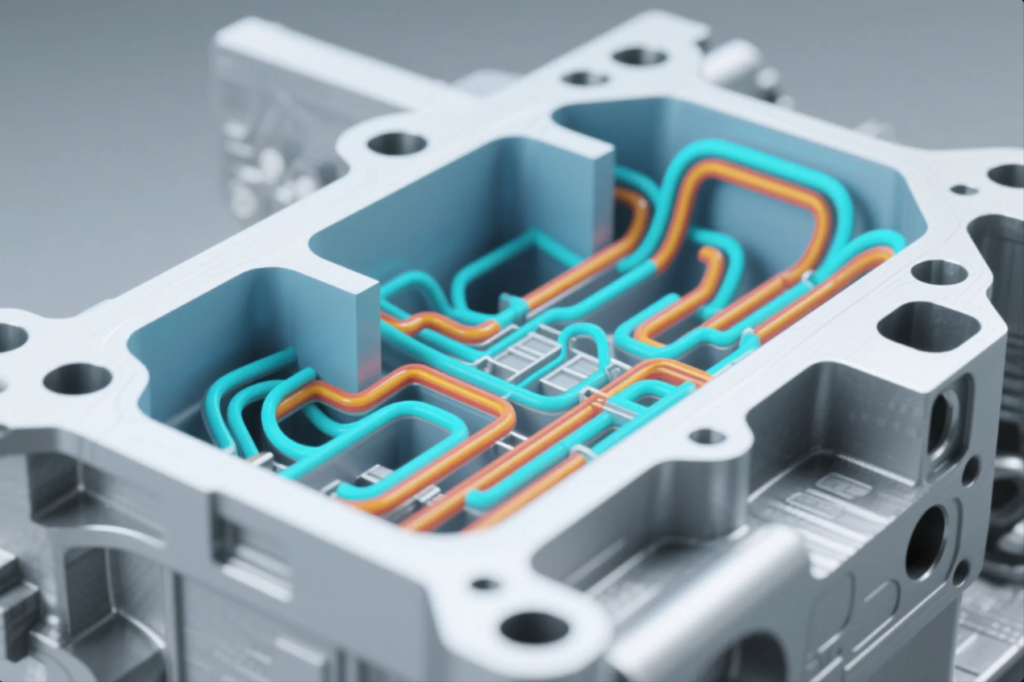
3. Inadequate Cooling Channel Placement
Poor cooling means longer cycle times—and more defects.
Many molds fail not from poor machining, but from bad thermal management. Cooling channels that are too shallow, too far, or unevenly spaced cause hotspots, shrinkage, and warpage.
| Mistake | Result | Best Practice |
|---|---|---|
| No conformal cooling | Uneven temperature | Use 3D printed cooling paths |
| One-sided channels | Warped parts | Symmetrical cooling loops |
| Poor flow direction | Longer cycle times | Reverse flow optimization |
Prime uses conformal cooling and copper inserts to reduce cycle time by 30%.
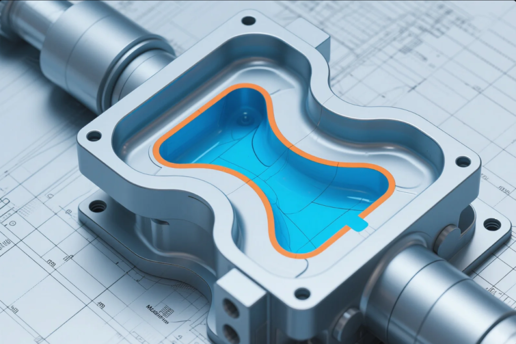
4. Overlooking Parting Line and Mold Flow
Misplaced parting lines cause flash and trapped air.
A clean parting line ensures easy mold separation and better surface quality. Mold flow analysis prevents misruns, air traps, and cold shuts.
| Design Feature | Risk | Solution |
|---|---|---|
| Poor parting line | Flash, leakage | Use flat, accessible faces |
| Gating at thin area | Misruns, cold shuts | Gate near thickest section |
| Sharp corners | Air entrapment | Add venting and fillets |
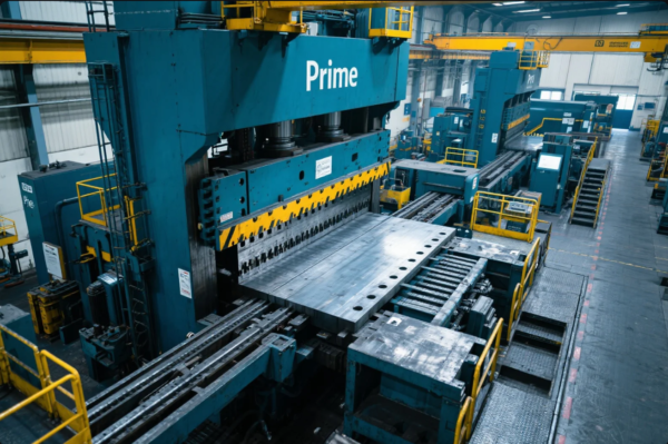
Every mold Prime builds is reviewed with simulation before machining.
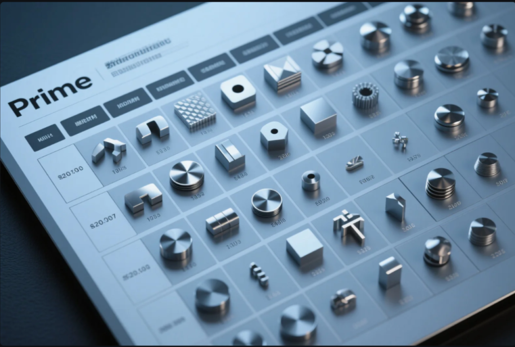
5. Selecting the Wrong Metal or Mold Material
Wrong material = premature failure.
If you’re casting aluminum into a low-grade steel mold, expect cracks. If you use aluminum molds for high-pressure zinc, they’ll wear out fast.
| Application | Recommended Mold Material | Reason |
|---|---|---|
| High-pressure die cast | H13 steel | Thermal shock resistance |
| Prototype molding | Aluminum 7075 | Fast machining, low volume |
| Medical injection | S136 stainless | Corrosion-resistant, polishable |
What is the best metal to mold?
Zinc and aluminum are easiest to mold, due to their flow properties and lower melting points.
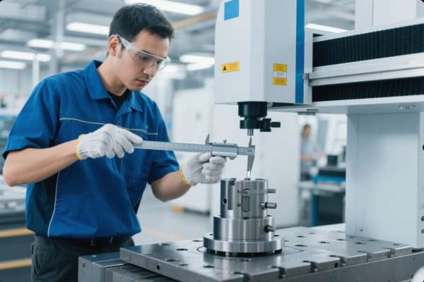
6. Not Considering Tolerances for Machining or Injection
Designing to ±0.001mm for a cast part? That’s a no-go.
Unrealistic tolerances drive up cost and machining time. For casting, expect ±0.1–0.3 mm. For precision CNC machining, ±0.01 mm is standard.
| Process | Realistic Tolerance Range |
|---|---|
| Die casting | ±0.10–0.25 mm |
| Sand casting | ±0.25–0.75 mm |
| CNC post-machining | ±0.005–0.02 mm |
Prime always confirms tolerance standards before quoting or building.
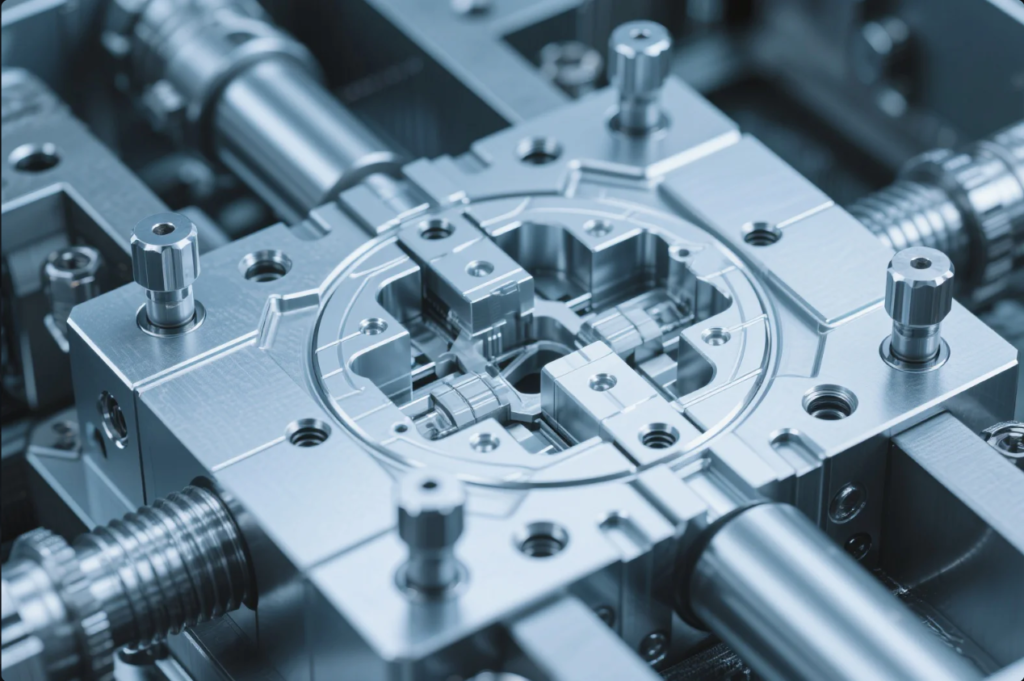
7. Lack of Maintenance Access and Modularity
When something breaks, can you fix it fast?
A good mold includes wear part access, removable inserts, and clear venting paths. Without this, maintenance requires full teardown.
| Feature | Maintenance Time | Downtime Saved |
|---|---|---|
| Modular insert system | 1–2 hours | Days |
| Integrated wear blocks | Replaceable | No remachining |
| External vent ports | Easy to clean | No disassembly |
FAQs
Q: What metals are easiest to mold?
A: Zinc and aluminum have low melting points and excellent fluidity.
Q: What should be avoided in mold design?
A: Thin unsupported walls, sharp corners, no draft angles, and complex undercuts without ejection plan.
Q: What’s the best mold material to avoid sticking or wear?
A: H13 steel with a nitrided surface or S136 stainless with high polish.
Q: Can Prime fix design errors before tool cutting?
A: Yes. We provide DFM and Moldflow review for every new project.
Q: Is there a design checklist I can use?
A: Yes. Contact us for a free mold design checklist and consultation.
Conclusion
Avoiding design mistakes in custom molds saves time, cost, and quality loss before they happen.
📩 Email: [email protected]
🌐 Visit: https://primecustomparts.com
With ISO-certified QA, simulation-based DFM, and over 30 years of mold-making expertise, Prime ensures your mold is right from the first shot.