Top Software Tools for Designing Custom Metal Molds Efficiently?
Manual die design is slow, prone to errors, and lacks scalability.
In 2025, designing custom metal molds without specialized software is nearly impossible. Leading CAD, CAM, CAE, and simulation tools now offer integrated die design, real-time collaboration, and virtual prototyping. These tools help engineers reduce lead time, improve quality, and optimize material usage before any steel is cut.
This article explores the top software solutions used by professionals for custom mold and die design—based on usability, speed, simulation accuracy, and compatibility with machining processes.
Table of Contents
- 1. What is Die Design in Custom Mold Manufacturing?
- 2. What Are Metal Dies Used For in Industry?
- 3. Why is Steel the Primary Material for Making Dies?
- 4. How Are Dies Manufactured from CAD to Machining?
- 5. Best Software for Efficient Custom Die and Mold Design in 2025
- FAQs
- Conclusion
1. What is Die Design in Custom Mold Manufacturing?
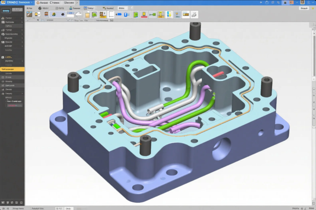
Die design refers to the detailed planning of a mold’s structure, including:
- Parting line definition
- Cavity/core block geometry
- Cooling channel layout
- Ejection system
- Gating and runner configuration
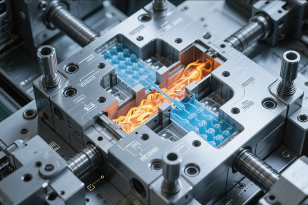
It connects product function with manufacturing feasibility. A poor die design leads to warping, misruns, and flash—causing part rejection and long cycle times.
2. What Are Metal Dies Used For in Industry?
Metal dies are essential for:
- Stamping parts in automotive and appliances
- Die casting aluminum and zinc parts
- Injection molding plastic and thermoset parts
- Coining, embossing, and trimming
They convert raw material into finished forms through shape retention and precise tolerances.
3. Why is Steel the Primary Material for Making Dies?

Tool steel (like P20, H13, and S136) is used for dies due to:
- High wear resistance
- Dimensional stability under heat
- Machinability and polishability
- Long service life (>1 million cycles)
Aluminum dies are used in prototyping or low-volume runs but wear faster and can’t handle high injection pressures.
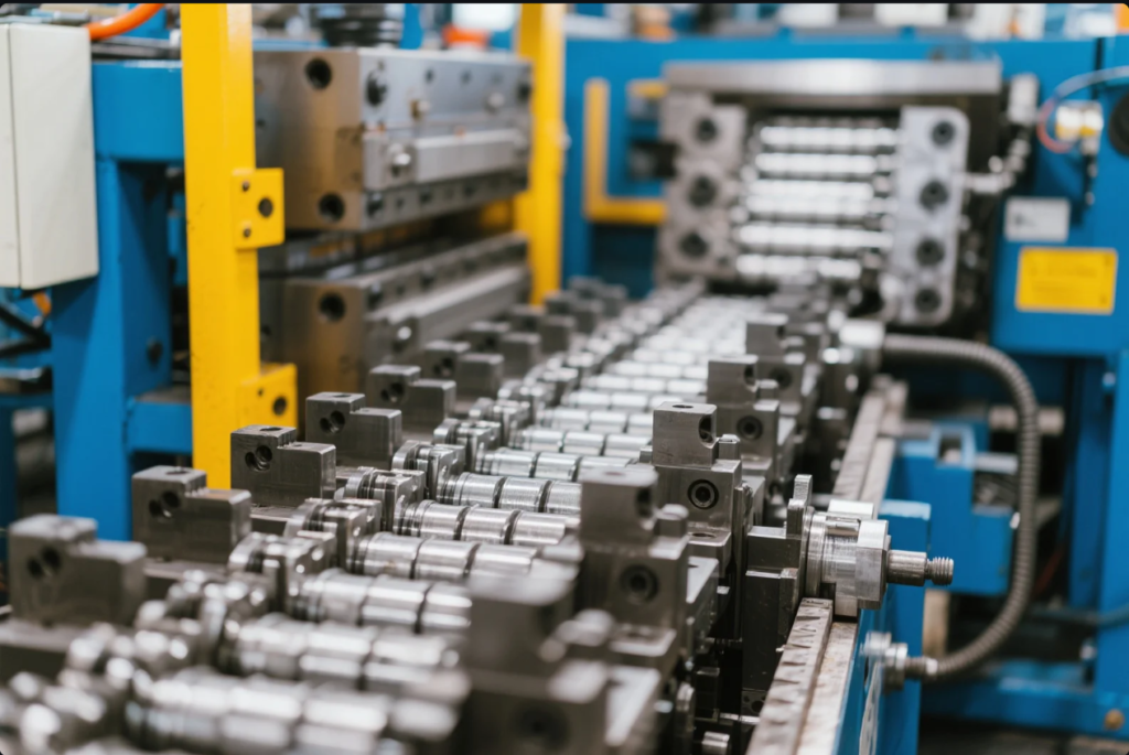
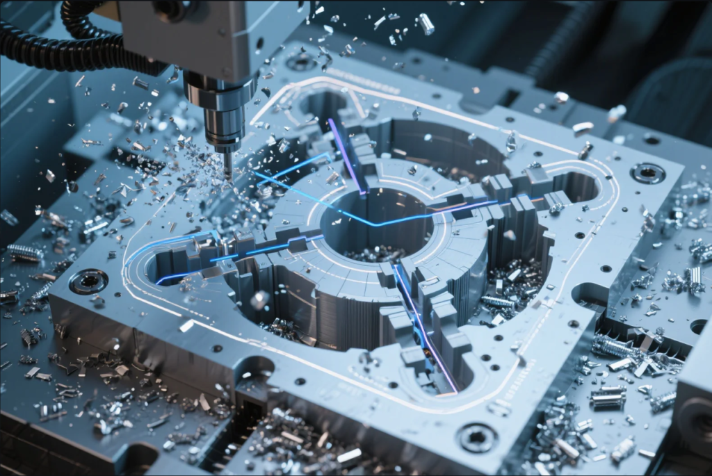
4. How Are Dies Manufactured from CAD to Machining?
Modern die manufacturing includes:
- 3D CAD Design using software like SolidWorks, NX, or CATIA
- CAM Programming to generate tool paths for CNC or EDM
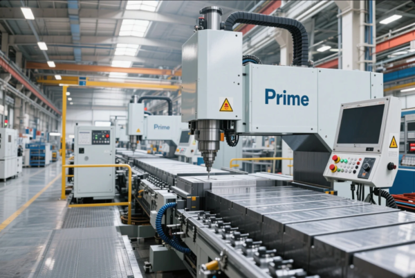
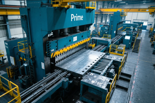
- Machining with 3/5-axis CNC mills, grinders, and EDM
- Fitting and Assembly of core/cavity, ejectors, lifters
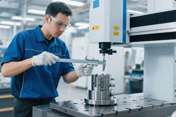
- Mold Trials and First Article Inspection (FAI)
Software now integrates these stages into a unified pipeline.
5. Best Software for Efficient Custom Die and Mold Design in 2025
Top Software Solutions:
| Software | Core Function | Website |
|---|---|---|
| SolidWorks | Parametric 3D CAD & Mold Tools | solidworks.com |
| Autodesk Moldflow | Plastic flow simulation | autodesk.com |
| Siemens NX | High-end mold/die CAD+CAM | plm.automation.siemens.com |
| CATIA | Aerospace-grade surface design | 3ds.com |
| PowerMill | 5-axis CAM and toolpath control | autodesk.com/powermill |
Software Features That Boost Efficiency:
- Parametric updates (no redraws needed)
- Cavity/core extraction
- Shrinkage compensation
- Cooling and warpage simulation
- Interference detection
At Prime, our engineers use SolidWorks for mold design, Moldflow for simulation, and PowerMill for CAM—ensuring accuracy from design to final milling.
FAQs
Q: What is a die design in mold making?
It’s the process of designing cavity, core, cooling, and ejection systems to create consistent parts.
Q: What are dies used for?
They form or cut metal or plastic into desired shapes through stamping, casting, or molding.
Q: Why use steel for die tools?
Because of its durability, strength, and thermal stability—ideal for high-pressure operations.
Q: How is a mold die manufactured?
Via CAD modeling, CNC machining, EDM processing, fitting, and testing.
Conclusion
Modern die design is impossible without advanced software tools. The right CAD/CAM/CAE platform saves time, improves quality, and reduces rework.
📩 Want a mold design consultation? Contact us: [email protected]
🌐 Learn more or request a quote: https://primecustomparts.com
Prime combines expert engineers, certified tool steel, and advanced software to deliver precision molds—faster and smarter.