How to Meet Tight Tolerances in Precision Metal Stampings

Table of Contents
- Tolerance Levels: ±0.05 mm vs. ±0.01 mm
- Key Influencing Factors for Achieving Tight Tolerance
- Tooling Design and Die Maintenance Strategies
- In-Process Inspection and First-Article Testing
- Case Study: Maintaining ±0.025 mm in Surgical Components
- Prime’s Engineering Support & Quality Framework
- Best Practices for Buyers
- FAQs for Buyers
- Conclusion & Contact Information
Tolerance Levels: ±0.05 mm vs. ±0.01 mm
60% of metal stamping buyers consider tolerance the single most important spec. Let’s define levels:
- ±0.05 mm fits general applications like enclosures or brackets.
- ±0.01 mm suits surgical, aerospace, or microelectronic components.
Achieving these ranges demands control across every manufacturing step.
References:
Key Influencing Factors for Achieving Tight Tolerance
Materials and Environment
- Flat, clean coils from Baosteel, Thyssenkrupp
- Consistent temperature (20±1°C) and humidity in factory
Tooling Design
- CAD simulations using SolidWorks, UG NX
- Replaceable inserts, hardened guides, minimal play
Press Equipment
- Closed-loop servo presses
- Real-time tonnage sensors, thermal controls
Inspection Integration
- Keyence vision systems for live inspection
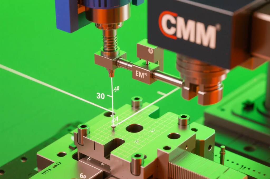
- CMM equipment for dimensional reports
Tooling Design and Die Maintenance Strategies

Design Principles
- Feature positioning based on FEM
- Die clearance tuned for specific materials
- Alignment via shoulder bushings
Maintenance Strategy
- Daily: clean, re-lube
- Weekly: visual wear review
- Monthly: insert checks
- Quarterly: surface regrind and hardness tests
In-Process Inspection and First-Article Testing
Continuous Monitoring
- Sensor tracking of press force
- SPC software logging measurements
- Triggered shutdown on tolerance drift
First Article Inspection (FAI)
- CMM checks first 10 pieces
- FAI per PPAP guidelines
- CMM overlay and SPC graphs generated
Case Study: Maintaining ±0.025 mm in Surgical Components
Background
Client needed 10,000 surgical clips with ±0.025 mm flatness and no burrs.
Execution
- Material: 316L stainless
- Die: Progressive, with thermal control
- Equipment: Servo press with feedback loop
- Inspection: CMM and vision every 500 pcs
- Packaging: Sealed Air moisture-controlled

Results
- ±0.025 mm achieved in 100% parts
- 99.95% yield
- Project expanded to 3 other components
Prime’s Engineering Support & Quality Framework
Certifications & Process
- ISO 9001
- Traceable batch IDs
- Operator-level SOPs
- CAPA logs for any deviation
Digital Traceability
- Die #, coil ID, shift ID on each label
- Linked to part inspection and packaging data
Best Practices for Buyers
- Submit CAD files (STEP, IGES)
- Define tolerance zones clearly
- Specify test frequency
- Confirm FAI and PPAP requirements
- Request maintenance and inspection templates
- Ask for CPK and run charts for ongoing production
Additional guidance:
FAQs for Buyers
Q: Can you reach ±0.01 mm in copper?
A: Yes, with hardened tools and 0.5 mm+ thickness.
Q: Do you inspect 100%?
A: Vision systems check every 10 pieces; SPC triggers full inspection when needed.
Q: Are reports customizable?
A: Yes. PDF, Excel, barcode format available.
Q: Do you offer plated finishes?
A: Yes, including bright nickel, tin, black oxide, passivation.
Q: What’s your tooling lifetime?
A: 500K–1M+ strokes depending on material and die care.
Conclusion & Contact Information
To meet ±0.01 mm tolerances, every detail matters—from die design to environmental control to inspection strategy. Prime delivers tight-tolerance parts for aerospace, electronics, and med-tech—on time, every time.
📧 Email: [email protected]
🌐 Website: https://primecustomparts.com
Reach out for a free DFM review, quotation, or sample consultation.