TEMPLATE_START
How Can You Identify If a Part Was Cast?
After inspecting thousands of metal components, we've developed reliable methods to distinguish cast parts from alternatives - crucial for quality control and reverse engineering.
Look for these 6 signs of casting: 1) Surface texture variations 2) Parting lines 3) Gate/runner marks 4) Draft angles 5) Internal porosity (visible in X-ray) 6) Grain structure differences - each revealing clues about the manufacturing process.
These identification techniques could save you from costly production mistakes.
What Surface Features Reveal Casting Origins?
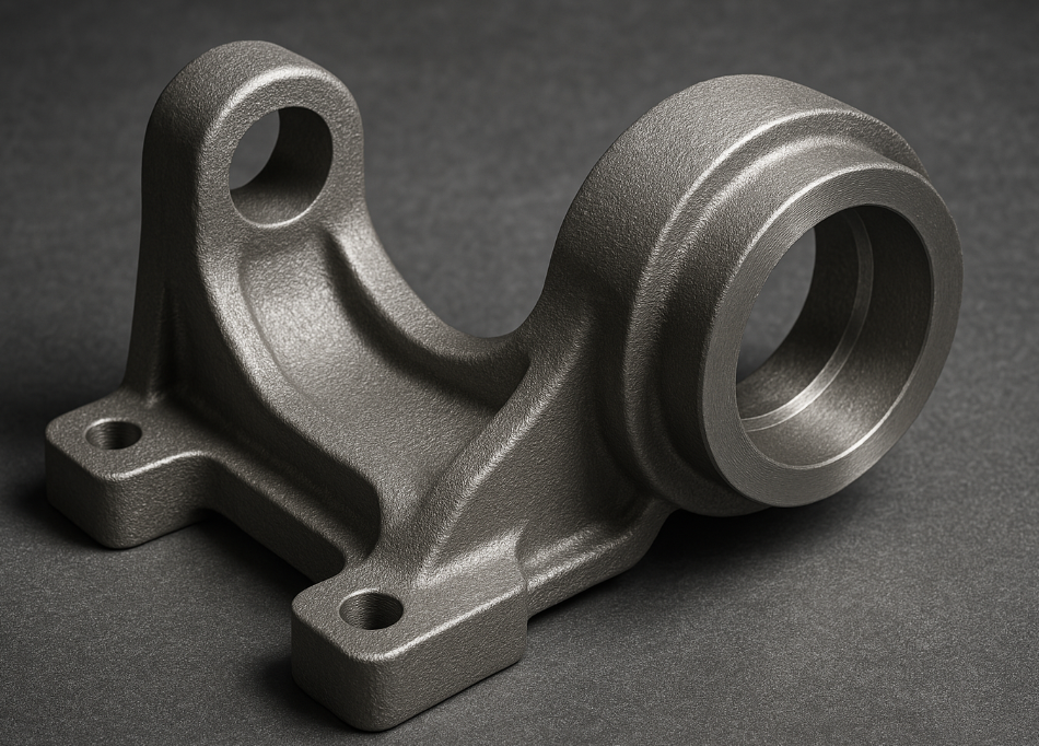
The skin of a metal part tells its production story.
Cast surfaces show: 1) Slightly rough "orange peel" texture (50-250µm Ra) 2) Visible mold material impressions 3) Non-uniform reflectivity 4) Circular flow marks from molten metal - contrasting with machined surfaces' tool marks or stamped parts' sheen edges.
Surface Comparison Guide
| Feature | Cast | Machined | Stamped | Forged |
|---|---|---|---|---|
| Texture | Rough | Tool marks | Smooth | Directional grain |
| Edges | Rounded | Sharp | Burred | Radiused |
| Reflectivity | Matte | Uniform | Glossy | Mixed |
| Imperfections | Porosity | Tool lines | Wrinkles | Flow lines |
Measurement Data
| Process | Typical Ra (µm) | Dimensional Tolerance | Corner Radius |
|---|---|---|---|
| Sand Cast | 6.3-25 | ±0.5mm | 1-3mm |
| Die Cast | 1.6-6.3 | ±0.1mm | 0.25-1mm |
| CNC Machined | 0.4-3.2 | ±0.02mm | 0.1mm |
| Forging | 3.2-12.5 | ±0.3mm | 2-5mm |
Detection Methods
- Visual inspection: 10x magnifier for surface patterns
- Tactile test: Castings feel slightly grainy
- Rubbing test: Leave different powder residues
How Do Part Lines and Marks Indicate Casting?
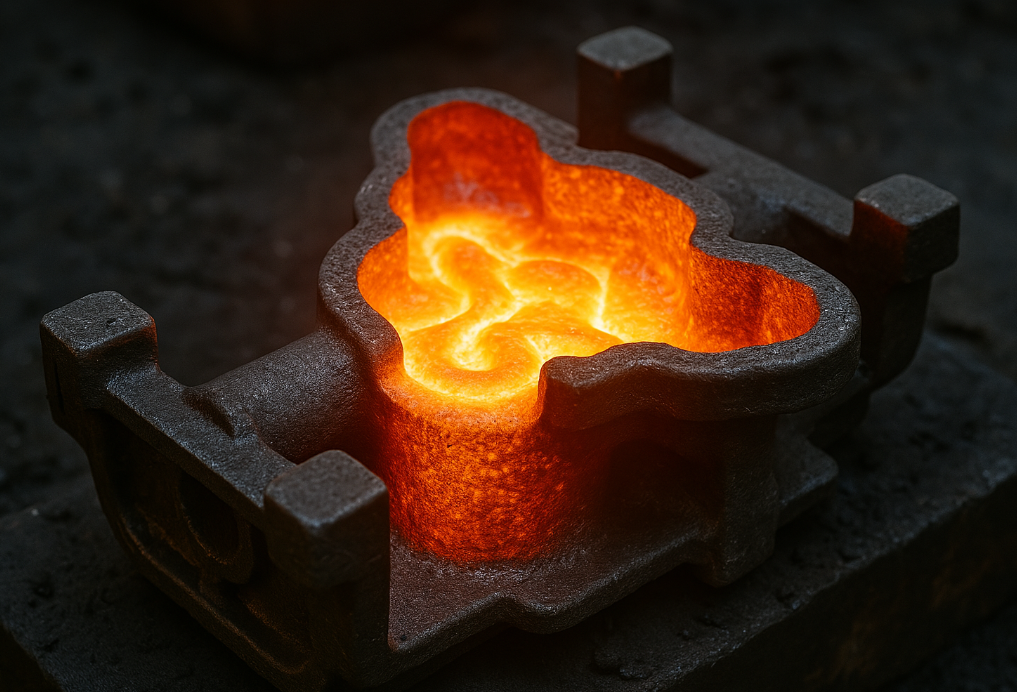
Mold separation creates permanent casting fingerprints.
All cast parts display: 1) Parting lines (seams where mold halves met) 2) Ejector pin marks (small circular indentations) 3) Gate/runner vestiges (uneven protrusions) - with locations varying by casting method (sand, die, investment, etc).
Casting Mark Identification
| Feature | Sand Casting | Die Casting | Investment Casting |
|---|---|---|---|
| Parting Line | Visible, rough | Precisely matched | Minimal/no line |
| Gate Mark | Large irregular | Small truncated | Carefully removed |
| Ejector Pin | Rare | Multiple round | None |
| Draft Angle | 1-3° | 0.5-2° | Near zero |
Tooling Mark Measurements
| Mark Type | Typical Size | Location Pattern | Removal Methods |
|---|---|---|---|
| Parting Line | 0.1-1mm wide | Follows parting plane | Grinding |
| Ejector Pin | 2-8mm diameter | Evenly spaced | Machining |
| Gate | 3-20mm wide | Near thick sections | Cutting |
| Vent Marks | Hairline | Part edges | Polishing |
Process-Specific Signs
- Sand casting: Shows sand grain impressions
- Die casting: Has slight flash on edges
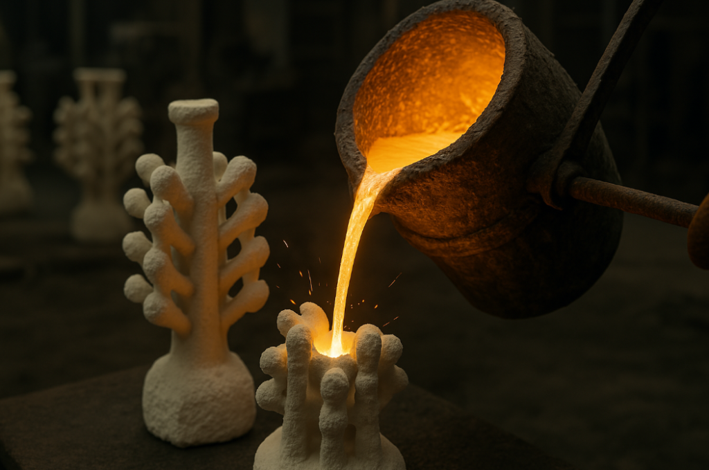
- Investment: Reveals ceramic shell texture
Why Does Internal Structure Reveal Casting?
Metallurgical analysis provides definitive proof.
Under microscope/X-ray, cast metal shows: 1) Dendritic grain structure 2) Random orientation 3) Porosity (0.1-5% void area) 4) Non-uniform composition - versus wrought metal's streamlined grains from mechanical working.
Metallurgical Differences
| Characteristic | Cast Structure | Wrought Structure |
|---|---|---|
| Grain Shape | Dendritic | Elongated |
| Grain Size | Large | Small/medium |
| Orientation | Random | Directional |
| Defects | Porosity, inclusions | Fewer defects |
Quantitative Analysis
| Test Method | Cast Result | Machined Result |
|---|---|---|
| Density | 95-99% theoretical | 99.5-100% |
| Hardness (HB) | Lower | Higher |
| Tensile Strength | 80% of wrought | 100% |
| Elongation (%) | Reduced | Improved |
Inspection Techniques
- Radiography: Shows porosity distribution
- Ultrasound: Detects internal discontinuities
- Chemical analysis: Higher oxygen in cast
How Does Part Design Reveal Casting Process?
Engineering features indicate manufacturing intent.
Design elements favoring casting include: 1) Uniform wall thickness 2) Generous corner radii 3) Avoidance of sharp details 4) Built-in draft angles 5) Minimized machining needs - contrasting with machined parts' design flexibility.
Design Feature Comparison
| Element | Cast Design | Machined Design |
|---|---|---|
| Walls | 3-15mm thick | Any thickness |
| Corners | R1mm minimum | Sharp possible |
| Holes | Cast-in cores | Drilled after |
| Surfaces | As-cast finish | Precise finish |
Dimensional Allowances
| Requirement | Casting Allowance | Machining Allowance |
|---|---|---|
| Draft Angle | 1-3° | None |
| Flatness | ±0.5mm/100mm | ±0.05mm/100mm |
| True Position | ±0.3-1.0mm | ±0.03-0.1mm |
| Surface Finish | 3.2-25µm Ra | 0.4-3.2µm Ra |
Process Limitations
- Minimum wall: 1.5mm (die cast) to 3mm (sand cast)
- Detail resolution: 0.25-0.5mm typically
- Undercuts: Require special cores
Conclusion
Identifying cast parts requires examining surface textures, parting lines, internal structures, and design features - with multiple verification methods confirming the manufacturing process used.
TEMPLATE_END