How far should a hole be from a sheet metal bend?
Placing a hole too close to a bend can crack your part—or break the tool.
As a rule of thumb, holes should be placed at least 2× the material thickness away from a bend. This prevents tearing, distortion, and tooling issues.
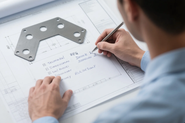
At Prime, we help clients optimize hole placement for clean bends, long tool life, and consistent part quality.
What is the minimum distance between hole slot to edge of the sheet?
Too-close holes can deform or cause burrs after bending.
The minimum distance between a hole or slot and the edge of the sheet should be at least 1.5× the material thickness. For precision parts, use 2× or more.
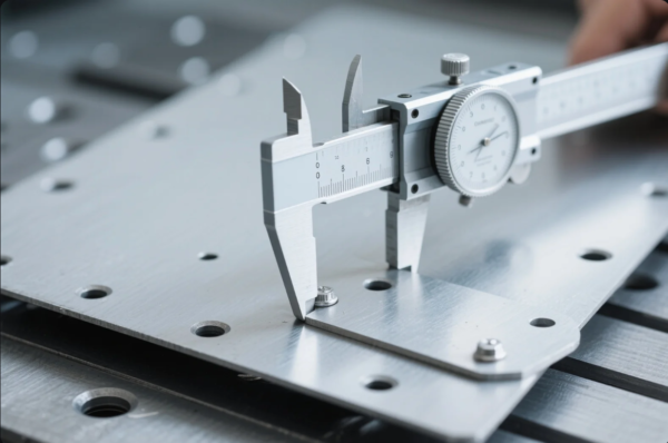
At Prime, we follow this spacing to ensure ISO-compliant sheet metal parts with sharp edges and smooth finishes.
Recommended Hole Edge Distances
| Material Thickness | Minimum Hole-to-Edge Distance |
|---|---|
| 1.0 mm | 1.5 – 2.0 mm |
| 1.5 mm | 2.25 – 3.0 mm |
| 2.0 mm | 3.0 – 4.0 mm |
| 3.0 mm | 4.5 – 6.0 mm |
We flag improper spacing during our DFM check to avoid post-bend failures or rework.
What is the bend rule for sheet metal?

A wrong bend rule can ruin form fit or function.
The standard bend rule is to use an inside bend radius equal to the material thickness and apply proper bend allowances based on the K-factor.
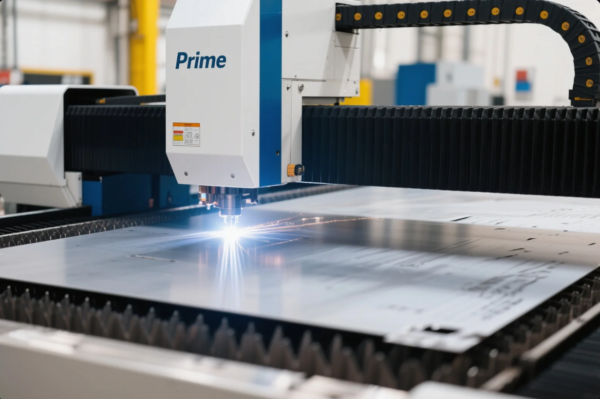
At Prime, we use bending software to calculate exact flat lengths and reliefs—ensuring your part folds right the first time.
Key Bend Design Rules
| Design Element | Standard Practice |
|---|---|
| Inside Radius | ≥ 1 × material thickness |
| Bend Allowance | Calculated using K-factor (≈0.3–0.5) |
| Bend Relief | Width = material thickness |
| Min Flange Length | ≥ 4 × material thickness |
Following these rules ensures crisp bends without cracking or wrinkling—especially on stamped and CNC-formed sheet parts.
What are the design considerations for bending sheet metal?
Designing without bend considerations leads to misfit and distortion.
Important factors include bend radius, bend direction, grain orientation, relief slots, and hole clearance.
At Prime, we help clients simplify part design while keeping it tool-friendly and production-ready.
Sheet Metal Bend Design Tips
| Consideration | Why It Matters |
|---|---|
| Bend Radius | Prevents cracking during forming |
| Grain Direction | Reduces breakage across bend lines |
| Hole Clearance | Avoids distortion near bends |
| Relief Slots | Eliminates tearing at corners |
| Tolerance Accumulation | Improves fit with mating parts |
We review all these points before tooling—saving clients both material and time.
What is the setback of sheet metal bending?
Setback isn’t guesswork—it’s critical to part accuracy.
Setback is the distance between the bend line and the tangent point of the bend. It’s used in calculating flat length and flange development.
At Prime, we automate setback and bend allowance calculations based on material, tooling, and bend angle. This gives you reliable results on every part run.
Setback Calculation Formula
Setback = (Tan(θ/2)) × (Inside Radius + K × Thickness)
| Bend Angle | Approx. Setback (1 mm thick, R=1 mm, K=0.4) |
|---|---|
| 90° | \~1.4 mm |
| 120° | \~1.9 mm |
| 135° | \~2.3 mm |
Correct setback ensures your flanges align as designed—without extra trimming or adjustment.
Conclusion
Leave at least 2× material thickness between holes and bends for safe, clean results.
Want expert help optimizing your sheet metal part? Prime offers free DFM checks, ISO-certified bending, and custom sheet metal production with fast turnaround and global shipping. Contact us today for a quote that’s accurate, fast, and production-ready.