Design for Manufacturability (DFM) in Custom Sheet Metal Components
In the fast-paced world of custom sheet metal fabrication, delivering precision components at scale is only possible when the design is optimized for the shop floor. That’s where Design for Manufacturability (DFM) comes in—a critical process that helps engineers and product designers create parts that can be produced efficiently, affordably, and reliably.
This guide provides a comprehensive overview of DFM for sheet metal designers, procurement engineers, and OEM developers. We’ll explore best practices for geometry, materials, tolerances, and collaboration with fabricators—ensuring your parts are production-ready from the first prototype to mass rollout.
What Is DFM and Why It’s Crucial for Sheet Metal Designers
Design for Manufacturability (DFM) ensures that parts are easy to fabricate with available tools, standard processes, and within budget. DFM also reduces waste, tooling issues, and engineering revisions.
DFM Benefits in Sheet Metal Fabrication
DFM is a foundation for lean, scalable manufacturing. The key benefits include:
- Fewer design errors and revisions
- Lower fabrication costs and faster quotes
- Smoother transition from design to production
- Less material waste due to optimized nesting
- Higher yield with better part repeatability
Learn more on Wikipedia – Design for Manufacturability
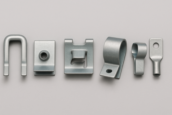
Best Practices for Hole Placement, Flange Height, and Material Thickness
Adhering to standard fabrication rules improves production speed and part accuracy.
✅ Hole Placement & Spacing
- Edge-to-hole distance: ≥ 2× material thickness
- Hole-to-hole spacing: ≥ 3× thickness
- Minimum hole size: ≥ material thickness
✅ Flange Height
- Minimum height = 2× thickness + internal radius
- Add reliefs near bends to avoid tearing

Common DFM Mistakes in Sheet Metal Design
Avoid these issues to streamline production:
- Specifying overly tight tolerances on non-critical features
- Designing sharp internal corners (should be radiused)
- Including holes too close to bends
- Adding cosmetic features that require special tooling
Reference tolerance standards: ISO 2768
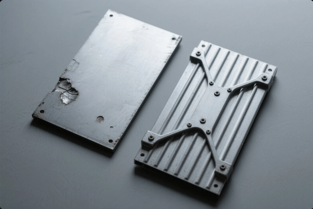
Avoiding Oil Canning and Warping in Large Panels
Oil canning is the visible distortion of large, flat sheet metal surfaces. It’s especially problematic in enclosures, doors, or control panels.
How to Prevent It:
- Use ribs, folds, or shallow bends for stiffness
- Increase sheet gauge when needed
- Add diagonal features or spot weld reinforcements
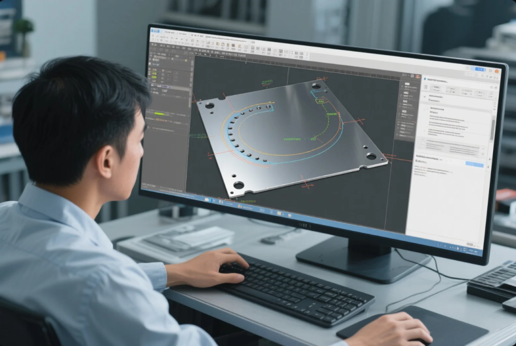
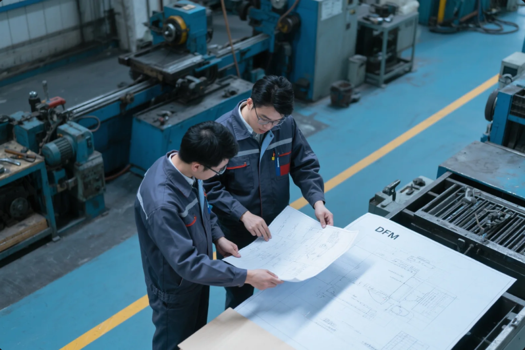
How to Collaborate with Fabricators for DFM-Approved Drawings
Working closely with your metal fabricator improves manufacturability and reduces mistakes.
What to Share:
- Flat pattern (DXF or DWG)
- 3D part model (STEP or SolidWorks format)
- Material specification
- Critical tolerances and finish expectations
- Notes on deburring, coating, welding, or assembly
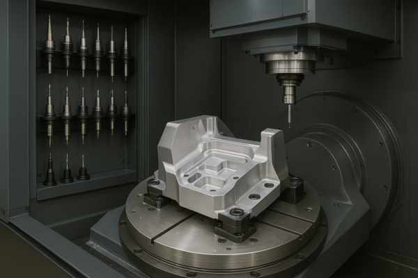
DFM for CNC, Laser Cutting, and Press Brake Bending
- CNC punching prefers standard hole shapes and common tooling sizes
- Laser cutting allows more complex geometries, but watch for kerf width
- Press brake forming requires minimum flange lengths and reliefs to avoid tearing
Use tab-and-slot joints where possible for self-locating assemblies.
DFM and Material Selection: Steel vs. Aluminum vs. Stainless
| Material | Pros | Cons |
|---|---|---|
| Mild Steel | Low-cost, easy to form | Prone to corrosion |
| Aluminum | Lightweight, corrosion resistant | Softer, needs tighter bend control |
| Stainless Steel | Strong, clean finish | High cost, hard to bend |
Browse material specs at MakeItFrom.com
Case Study: Redesigning a Server Cabinet for Manufacturability
Client: U.S.-based data center OEM
Challenge: Frequent warping, inconsistent fit, and long production time
Original Design Issues:
- 0.9 mm aluminum used for all panels
- No structural reinforcements
- Overly complex assembly with 6 parts
DFM Redesign Solutions:
- Upgraded to 1.5 mm steel for main frame
- Introduced bend flanges and internal ribs
- Reduced part count by integrating flanges
- Aligned all hole patterns with standard punch tooling
Results:
- 35% reduction in cost
- 70% faster assembly
- Zero rejected units in the first 10,000 pcs batch

FAQs
Q1: Can I apply the same design for CNC punching and laser cutting?
A: Partially. CNC requires standard hole sizes; laser offers more flexibility for complex shapes.
Q2: Is electropolishing required after laser cutting stainless?
A: Not always, but it helps in high-spec applications like food or medical devices.
Q3: Should I provide multiple revisions to my fabricator?
A: No. Share only the current version with version control clearly labeled.
Q4: What tolerance should I use for general sheet metal parts?
A: ISO 2768-m (medium) unless your feature is fit-critical (then specify tighter limits).
Contact Us
Need help turning your design into production-ready sheet metal components?
📧 Email: [email protected]
🌐 Website: https://primecustomparts.com
With over 20 years of experience, ISO-certified quality, and 10 production lines, Prime helps global OEMs deliver high-performance metal parts—on time, on spec, and optimized for cost-efficiency.