How do I specify custom casting parts and sand casting molds for reliable production?
Late tooling, ambiguous tolerances, and transit scuffs drain margins. I show the exact specifications buyers should set so sand-cast parts launch right the first time.Late tooling, ambiguous tolerances1, and transit scuffs drain margins. I show the exact specifications buyers should set so sand-cast parts2 launch right the first time.
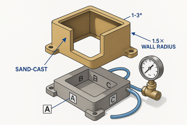
Specify alloy, annual volume, and tolerance class per ISO 8062-3. Set draft 1–3°, radii ≥1.5× wall, and minimum walls (Al 3–6 mm/0.12–0.24 in; iron 4–8 mm/0.16–0.31 in). Define machining allowances1 (1.5–3.0 mm/0.06–0.12 in), surface finish targets2, and inspection scope (FAI/CMM, heat-lot certs).
Below I detail where sand casting1 excels, how to choose mold media2, and a step-by-step troubleshooting path—with tables, checkpoints, and packaging rules buyers use.
Advantages of Using Sand Casting Molds?
Hard tooling punishes design changes1. Sand molds2 let you iterate quickly without sacrificing core performance.
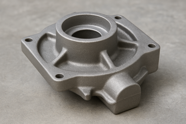
Sand casting gives fast, editable tooling1 for medium-to-large parts and low-to-mid volumes. Typical capability: ISO 8062-3 CT10–CT14 as-cast, 1–3° draft, and \~6.3–25 µm (250–1000 µin) Ra surfaces. Machine critical datums to reach tighter fits. Patterns modify inexpensively versus permanent dies, reducing risk during engineering churn.
Sand casting is my default when housings are bulky, passages require cores, or late ECNs are likely. I anchor expectations to ISO 8062-3 casting tolerance classes (CT). Most sand castings land CT10–CT14 as-cast; anything tighter is usually finished by machining. Surface finish depends on sand grain and binder system; \~6.3–25 µm Ra is common for green/no-bake per ASM International overviews. Draft at 1–3° prevents tear-out; internal radii at ≥1.5× wall smooth thermal gradients and feeding.
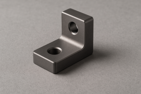
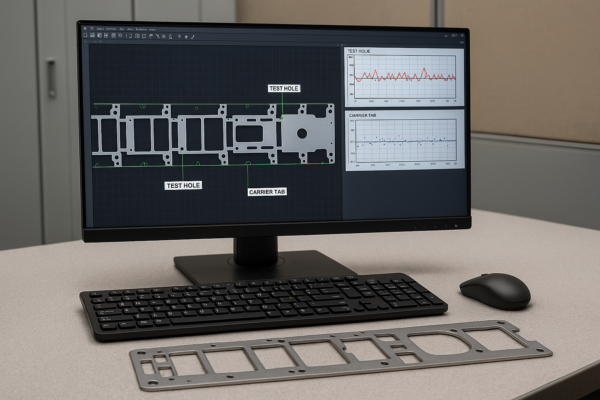
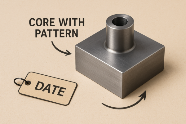
From a cost/lead-time standpoint, pattern boards in polyurethane or aluminum cut quickly, and edits take days—not weeks. I size risers with Chvorinov’s rule1 so they freeze last and feed shrinkage. I also plan machining stock early—often 1.5–3.0 mm (0.06–0.12 in) on faces and 1.0–2.0 mm (0.04–0.08 in) on holes/bosses—to guarantee datums without excessive passes. Where stability matters, we document a control plan: alloy certs, tensile/hardness per heat, FAI/CMM on critical dimensions, and defined blast media (e.g., S230 steel shot2 or A120 Al₂O₃).
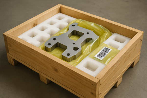
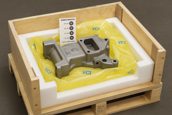
At Prime (China; founded 1993; ISO-certified; 10 production lines), I combine 24-hour DFM, quick pattern CNC, and inspection reports (FAI/CMM). For export, packaging is engineered—line-contact foam on machined faces, VCI bag + desiccant, humidity cards, and ISPM-15 heat-treated pallets per ISPM-15—to stop corrosion and edge bruising.
Upload your drawing to get 24-hour DFM advice1 and a quote; I’ll confirm whether sand casting2 is the best route before you commit.
Practical checkpoints buyers should verify
- Tolerance class (ISO 8062-3)1 and a machining map with datums A/B/C.
- Draft 1–3°, radii ≥1.5× wall, realistic minimum walls by alloy.
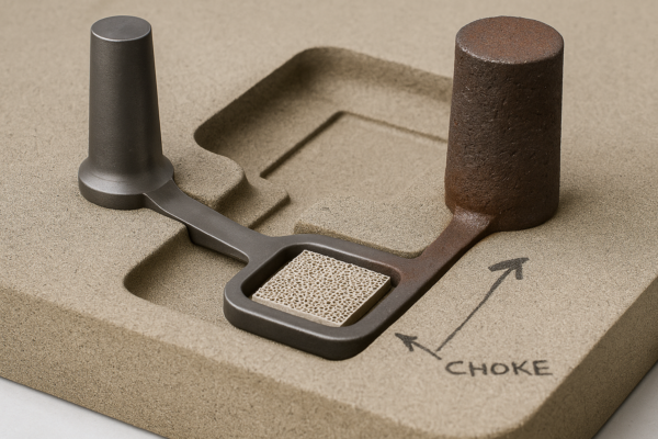
- Gating/risering simulation2 or feeder calculations reviewed and approved.
Quality & packaging notes buyers care about
- Require chemistry, tensile1, and hardness per heat; retain witness coupons.
- Define cosmetic vs. functional zones; specify blast media and masking.
- Use VCI + desiccant; cushion machined faces; ISPM-15 pallets2 with corner guards.
| Factor | Option A | Option B | What it means for cost/lead time |
|---|---|---|---|
| Process Route | Green sand1 | No-bake/shell | Green sand1 is fastest/lowest cost; no-bake improves finish/accuracy. |
| Pattern Material | PU board2 | Aluminum | PU edits quickly; aluminum holds detail and lasts longer. |
| Core System | PU cold-box | Sodium silicate | PU gives strong, accurate cores; silicate is cleaner but brittle. |
| Tolerance Feasibility | CT12–CT14 | CT10 with machining | Machining critical datums cuts assembly risk; adds cycle time. |
| Surface Finish | 12.5–25 µm Ra | 6.3–12.5 µm Ra | Finer finish trims machining passes; raises mold prep cost. |
| Testing/Reports | COA only | FAI + CMM | Higher confidence; extra inspection time and fees. |
Common Materials for Sand Casting Molds?
“Sand is sand” is a myth. Media and binders1 determine finish, stability, and defect risk2.
Choose base sand and binder by alloy and geometry. Silica is economical; olivine lowers thermal expansion; chromite resists metal penetration. Green sand (clay-water)1 is fast; chemical systems (furan/phenolic urethane, sodium silicate)2 boost strength and accuracy. Control GFN, moisture, permeability, and LOI using AFS/ASTM methods.
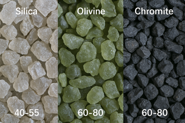
I specify sand by grain fineness number (GFN)1 and angularity, then pick binders fit for the job. Silica suits most non-ferrous work but expands around 573 °C, risking veining in ferrous hot spots. Olivine reduces expansion; chromite offers high refractoriness and resists penetration in steel or thin-wall ductile iron. For green sand, bentonite + water2 deliver speed and cost efficiency. When accuracy or long, slender cores matter, I prefer no-bake furan or phenolic urethane (PU); sodium silicate (CO₂-cured) is clean and collapsible but can be brittle.
I stabilize systems with measurable tests: sieve analysis and GFN per ASTM E11, permeability and compactability via AFS procedures, green compressive strength, and loss-on-ignition (LOI) (tracks residual organics from reclaimed sand). Keeping moisture in range curbs gas porosity; insufficient moisture causes erosion. A zircon/alumina refractory wash on critical faces improves finish and peel. The American Foundry Society is my standard reference for shop-floor control plans (AFS).
Typical recipes: A356 aluminum1 with PU cold-box cores, GFN 60–80, and de-gassed melt produces smooth internal passages; ductile iron2 benefits from chromite or blended sand at hot areas to curb veining; gray iron often runs well on silica plus a consistent wash. For pattern shrinkage allowance, I start with industry norms—Al alloys \~1.0–1.3%, gray/ductile iron2 \~1.0%, carbon steel \~2.0%—then confirm by pilot pours and CMM (general guidance summarized across **
In practice, mold media choices also reflect environmental and audit needs. Low-emission binders1 reduce smoke, and robust reclamation keeps LOI stable while cutting media cost. I ask suppliers for weekly sand reports2—moisture, compactability, permeability, strength, LOI, and sieve curves—and link those to dimension and surface capability on the FAI parts. When a vendor can show that thread, I trust their process window.
Upload your drawing to get 24-hour DFM advice1 and a quote; I’ll match a sand/binder recipe2 to your alloy, finish, and budget.
Practical checkpoints buyers should verify
- Target GFN, sieve curve1, moisture2, permeability, and LOI are trended weekly.
- Binder type/percentage and cure method listed on the router by feature.
- Core prints sized for handling strength and clean collapse at shakeout.
Quality & packaging notes buyers care about
- Ask for sand system SPC charts1 plus corrective actions on out-of-control points.
- Protect fragile cores/vents with custom dunnage2; mark “no-stack” zones.
- Verify shot-blast media type/size; prevent grit embedding on soft alloys.
| Factor | Option A | Option B | What it means for cost/lead time |
|---|---|---|---|
| Base Sand1 | Silica | Olivine/Chromite | Silica is economical; olivine/chromite manage heat and reduce penetration. |
| Binder2 | Green sand (clay) | Furan/PU, Sodium silicate | Chemical systems increase accuracy/core strength; add curing time. |
| Coating | None | Zircon/alumina wash | Wash enhances finish; adds drying/handling steps. |
| Reclaim Ratio | Low | High with LOI control | High reclaim cuts media cost but needs tight LOI control. |
| GFN | 40–55 | 60–80 | Coarser vents better; finer improves surface but risks gas defects. |
| Testing | Basic checks | Full AFS panel | Better stability; more QC time and cost. |
Troubleshooting Sand Casting Mold Issues?
Defects kill timelines. A repeatable diagnostic path1 saves rework and protects your schedule2.
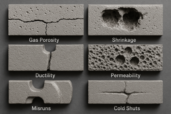
Classify defects: gas/porosity1, shrinkage, misrun/cold shuts, veining/penetration, or erosion/inclusions. Verify sand tests, melt temperature, and pattern/core alignment first. Improve venting and feeding, adjust coatings/media, or raise pour temperature within spec. Add NDT (PT/MT/UT)2 on critical lots to protect assemblies.
I always begin in the two places variation hides: the sand lab and the melt log. Pull moisture1, compactability, permeability2, green strength, LOI from the same shift as the defect. Compare superheat and pouring temperature to the alloy window. Confirm pattern alignment and core print contact; then check gate/riser orientation.
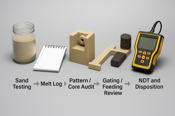
Disposition is a business call. I compare defects against machining stock and your tolerance class (ISO 8062-31): if stock covers it, salvage by machining; if not, recast. For critical parts, I specify NDT standards: penetrant testing (PT)2 per **
Upload your drawing to get 24-hour DFM advice1 and a quote; I’ll return a corrective action map2 and stabilized process window within one working day.
Practical checkpoints buyers should verify
- Pouring temperature/superheat1 and fill time recorded per heat and traceable to parts.
- Sand moisture/compactability/permeability/LOI2 within control limits at molding time.
- Riser necks, chills, and sleeves validated on hot spots; gating turbulence minimized.
Quality & packaging notes buyers care about
- Add NDT (PT/MT/UT)1 on first three lots; freeze the plan after capability proof.
- Deburr and break edges; protect with foam cells or molded pulp separators.
- Specify pallet style, max stack height, and corner protection; include VCI + humidity indicators2.
| Factor | Option A | Option B | What it means for cost/lead time |
|---|---|---|---|
| Defect Category | Gas porosity1 | Shrink porosity | Gas fixes: venting/LOI/de-gassing; Shrink fixes: riser modulus/sleeves/chills. |
| Melt Control | Low superheat | Within spec | Low superheat risks misruns; correct temps stabilize fill/microstructure. |
| Sand Choice | Silica only | Blended/Chromite | Blends curb veining/penetration at higher media cost. |
| Coating | None | Zircon wash2 | Coating reduces burn-on; adds drying time and control steps. |
| Inspection | Visual + COA | FAI + CMM + NDT | Higher confidence; increased inspection/documentation time. |
| Disposition | Machine salvage | Recast | Salvage cuts scrap but may extend cycle; recast resets lead time. |
Conclusion
Define alloy, tolerances, and mold media early; verify sand control and feeding; lock inspection and packaging—then send drawings for a 24-hour DFM review and quote now.
-
Understanding gas porosity can help improve product quality and reduce defects in manufacturing processes. ↩ ↩ ↩ ↩ ↩ ↩ ↩ ↩ ↩ ↩ ↩ ↩ ↩ ↩ ↩ ↩ ↩ ↩ ↩ ↩ ↩ ↩ ↩ ↩ ↩ ↩ ↩ ↩
-
Exploring zircon wash can enhance your knowledge of coating techniques that improve product durability and performance. ↩ ↩ ↩ ↩ ↩ ↩ ↩ ↩ ↩ ↩ ↩ ↩ ↩ ↩ ↩ ↩ ↩ ↩ ↩ ↩ ↩ ↩ ↩ ↩ ↩ ↩ ↩