How to Optimize Bend Radius and K-Factor for Accurate Sheet Metal Forming
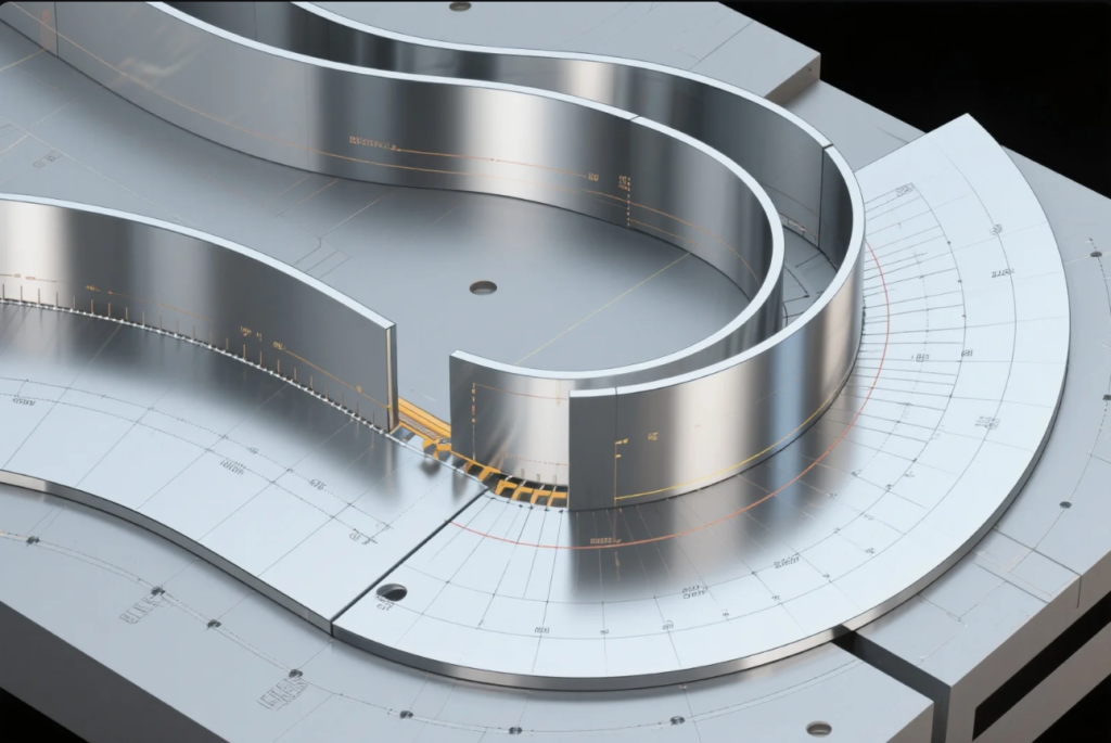
Precision in sheet metal forming doesn’t happen by accident—it begins with a deep understanding of two critical parameters: bend radius and K-Factor. These factors directly influence the success of sheet metal fabrication by affecting formability, accuracy, material stress, and final product performance.
Whether you’re an engineer, buyer, or project manager, optimizing these values ensures production efficiency and avoids costly errors during mass manufacturing.
What Is Bend Radius and Why It Matters in Sheet Metal Bending
The bend radius is the radius measured on the inner part of the sheet after it is bent. It is one of the most important factors affecting metal ductility, springback, and surface cracking.
Recommended Minimum Bend Radius by Material
| Material | Minimum Inside Radius |
|---|---|
| Aluminum 5052-H32 | 1.0 × Thickness |
| Stainless Steel 304 | 1.5 × Thickness |
| Cold Rolled Steel A1008 | 1.0 × Thickness |
| Brass C260 | 0.8 × Thickness |
Learn more about aluminum bending standards from The Aluminum Association.
Understanding K-Factor: The Link Between Neutral Axis and Accuracy
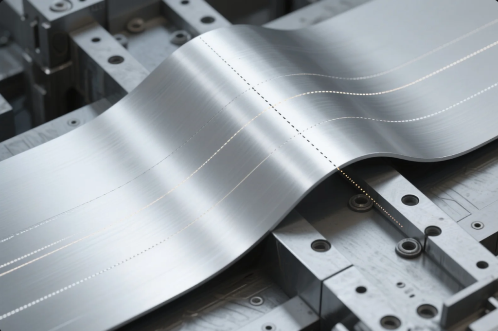
The K-Factor describes how the neutral axis shifts during a bend. It is defined as:
$$
K = \frac{\text{Distance to Neutral Axis}}{\text{Material Thickness}}
$$
A correct K-Factor ensures accurate flat pattern development and predictable forming.
How to Calculate the Right K-Factor Based on Material Thickness
K-Factor depends on:
- Material properties
- Thickness
- Bending method (air, bottoming, coining)
- Die opening and punch radius
Step-by-Step Calculation
Use Sheet Metal Bending Calculator by Machinery Handbook to estimate bend allowance, K-Factor, and bend deduction.
Using CAD Tools to Minimize Bending Errors and Improve Production Quality
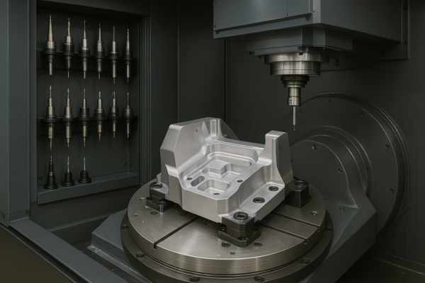
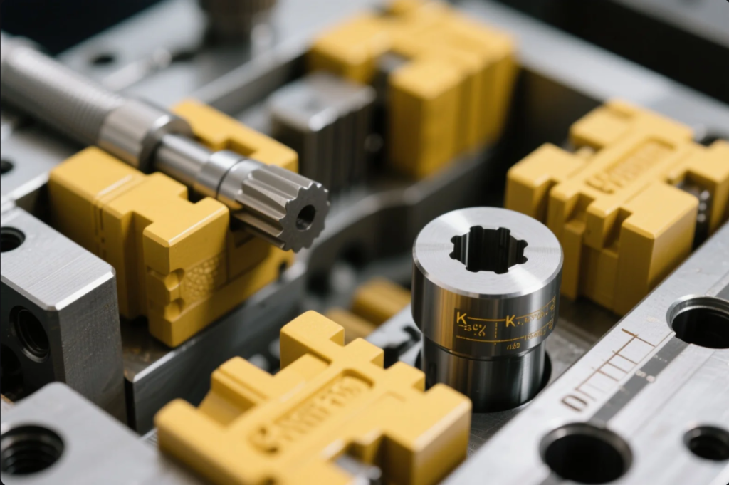
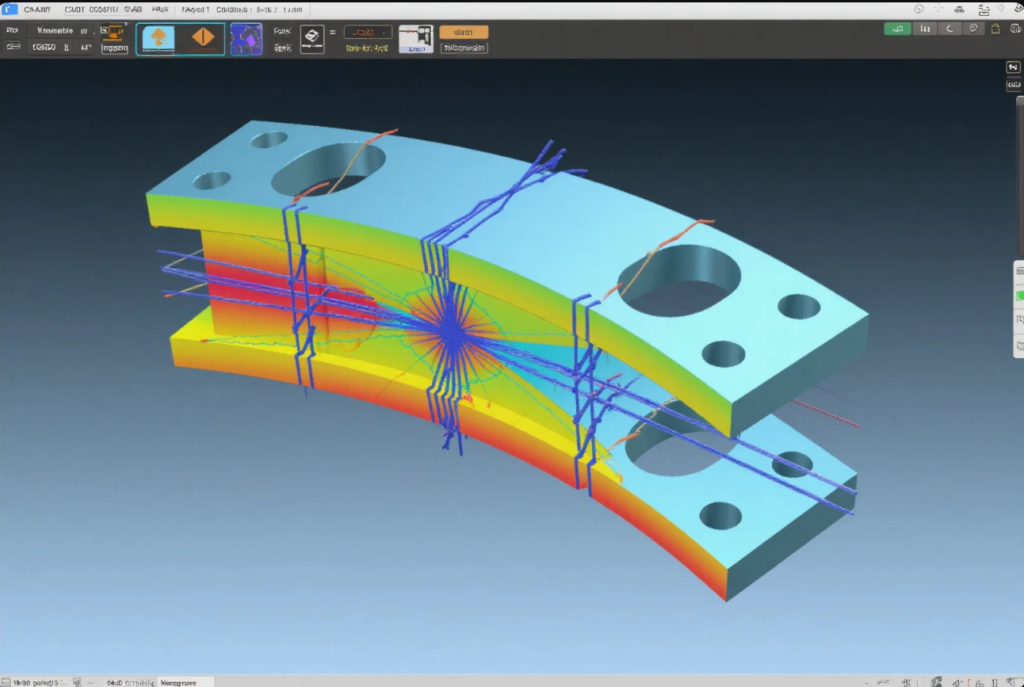
Modern software tools can simulate and correct forming issues before production.
- Autodesk Fusion 360 Sheet Metal Guide
- SolidWorks Bend Deduction Calculator
- Dassault Systèmes Metal Forming Solutions
Common Mistakes in Bend Radius and K-Factor Calculations
Avoid these common pitfalls:
- Using incorrect K-Factor for tooling type
- Ignoring material grain direction (see why it matters)
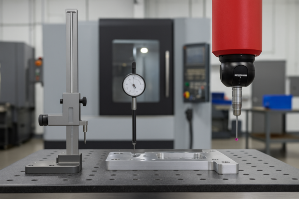
- Not validating CAD results with sample bending
✅ Tip: Always prototype the first batch and compare with flat pattern predictions.
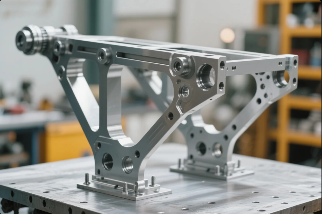
Case Study: Bending Optimization in Aerospace Bracket Production
Client: Aerospace OEM
Problem: 7075-T6 brackets cracked during forming
Solution: Adjust bend radius from 1× to 1.5× thickness and recalibrate K-Factor to 0.47
Result: Scrap reduction of 90%, full AS9100 compliance
FAQs
Q1: Where can I learn more about sheet metal design standards?
A: Refer to the American Welding Society, SMACNA Sheet Metal Manual, and ISO 2768 standard.
Q2: Can I use one K-Factor for all jobs?
A: No. It changes based on material, thickness, and tooling.
Q3: Is K-Factor the same as bend allowance?
A: No. K-Factor is used to calculate bend allowance, but they are not interchangeable.
Q4: How does Prime help with optimization?
A: We use CAD simulations, tooling analysis, and trial runs to optimize bend quality for mass production.
Contact Us
Looking to optimize your OEM sheet metal parts with precision, speed, and reduced cost?
📧 Email: [email protected]
🌐 Website: https://primecustomparts.com
With over 20 years of experience and ISO-certified production lines, Prime helps global manufacturers deliver high-precision metal parts faster and better.

