Metal Stamping Parts: The Definitive Buyer\’s Guide for Engineers and Procurement Professionals
I. Introduction
Welcome to the definitive buyer\’s guide for metal stamping parts, meticulously crafted for engineers, designers, and procurement professionals. Metal stamping is a cornerstone of modern manufacturing, enabling the cost-effective production of complex metal components at scale. However, navigating the intricacies of design, material selection, process capabilities, supplier qualification, and quality assurance can be challenging. An error in specification or supplier choice can lead to costly delays, quality issues, and suboptimal product performance. This guide serves as your comprehensive resource for mastering the procurement and specification of metal stamping parts. Whether you are designing a new component, sourcing parts for an existing product, or aiming to optimize your supply chain, this document provides the critical knowledge and practical tools needed for success. We will cover everything from fundamental stamping principles and design best practices to developing technical specifications, analyzing costs, evaluating suppliers, and ensuring quality. By leveraging the insights and frameworks presented here, you will be empowered to: – Optimize part designs for manufacturability and cost-efficiency.
- Select the most appropriate materials and stamping processes.
- Develop clear and comprehensive technical specifications (RFQs).
- Understand and negotiate cost factors effectively.
- Implement robust supplier evaluation and selection processes.
- Ensure consistent quality through effective QA strategies.
Navigate this guide using the structured sections below to find the specific information you need to make informed decisions and achieve superior outcomes in your metal stamping projects.
II. Understanding Metal Stamping Fundamentals
A solid grasp of the basics is essential before diving into specifications and sourcing. ### Process Definition and Types
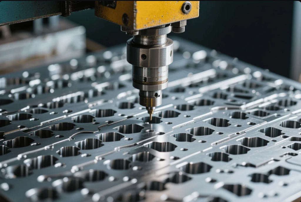
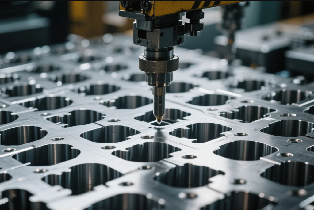
Metal stamping is a cold-forming manufacturing process that uses specialized tooling (dies) installed in a press to shape flat sheet metal into desired geometries. Key processes include: – Progressive Die Stamping: Sequential operations on a metal strip fed through a multi-station die. Ideal for high-volume, complex parts. (See Article 1 for detailed explanation)
- Deep Draw Stamping: Forming hollow, seamless parts by drawing a blank into a die cavity. Used for cups, cans, enclosures. (See Article 1)
- Transfer Die Stamping: Individual parts are transferred between stations. Suited for larger parts or those needing operations on multiple surfaces. (See Article 1)
- Four-Slide/Multi-Slide Stamping: Uses multiple slides acting from different directions. Excellent for intricate wire forms and small, complex parts. (See Article 1)
- Fine Blanking: Precision blanking process producing smooth, square edges, often eliminating secondary operations. (See Article 1)
- Compound Die Stamping: Performs multiple cuts or forms in a single press stroke, often used for simpler parts like washers.
- Short-Run Stamping: Utilizes lower-cost, adaptable tooling for prototypes and low-volume production.
**Process Selection Decision Tree:**(A visual decision tree graphic would be ideal here, guiding selection based on volume, complexity, precision, part size, and features. Text description: Start with required volume. High volume? Consider Progressive/Transfer. Low volume? Consider Short-Run. Complex bends? Consider Four-Slide. Deep hollow shape? Consider Deep Draw. High edge precision? Consider Fine Blanking.)### Key Terminology Glossary
- Blank: A piece of sheet metal cut to a specific size or shape before stamping.
- Blanking: Cutting the desired shape (the part) out of the sheet metal.
- Piercing: Punching holes or slots into the part.
- Forming: Bending or shaping the metal without intentionally changing its thickness.
- Drawing: Stretching metal over a form or into a die cavity, often resulting in wall thinning.
- Coining: Compressing metal in a confined die to produce fine details or impart hardness.
- Embossing: Creating raised or recessed designs in the metal surface.
- Die: The specialized tool set used in the press to cut and form the metal.
- Punch: The component of the die that applies force to cut or form the metal.
- Stripper: A mechanism that removes the material strip or part from the punch after an operation.
- Burr: A sharp ridge of metal raised on the edge of a part during cutting or piercing.
- Springback: The tendency of formed metal to partially return to its original shape after the forming pressure is removed.
- Work Hardening (Strain Hardening): Increase in metal hardness and strength due to plastic deformation during cold forming.
- Galling: Adhesive wear caused by friction between the tooling and workpiece material.
- DFM: Design for Manufacturability.
- GD&T: Geometric Dimensioning and Tolerancing.
- RFQ: Request for Quotation.
- SPC: Statistical Process Control.
Metal Stamping vs. Alternative Manufacturing Methods
| Choosing the right manufacturing process is crucial for cost and performance. Comparison Table: | — | |||||||||
|---|---|---|---|---|---|---|---|---|---|---|
| Process | Cold forming sheet metal | Subtractive removal | Molten metal injection | Additive layer building | ||||||
| Material | Sheet metals | Metal blocks/bars | Specific casting alloys | Metal powders | ||||||
| Complexity | High (formed features) | Very High (intricate shapes) | High (complex internal) | Very High (organic shapes) | ||||||
| Tooling Cost | High (dies) | Low-Moderate (fixtures/tools) | Very High (molds) | None | ||||||
| Per-Part Cost | Very Low (at high volume) | High | Moderate (at high volume) | Very High | ||||||
| Production Speed | Very High | Slow | High | Very Slow | ||||||
| Volume Suitability | Medium to Very High | Low to Medium | High to Very High | Prototype to Low | ||||||
| Material Waste | Moderate (scrap skeleton) | High (chips) | Low | Very Low | ||||||
| Typical Tolerance | ±0.025mm to ±0.2mm | ±0.005mm to ±0.05mm | ±0.05mm to ±0.5mm | ±0.1mm to ±0.3mm |
Decision Matrix: Stamping excels for medium-to-high volumes of parts made from sheet metal where tooling costs can be amortized. Machining is better for low volumes, extreme precision, or parts made from blocks. Casting is suited for complex 3D shapes in high volumes using specific alloys. 3D printing is ideal for prototypes and highly complex, low-volume parts. ## III. Design Guidelines for Metal Stamping Parts
Designing parts with stamping in mind is critical for success.
Material Selection Guidelines
- Define Requirements: Clearly identify necessary mechanical properties (strength, hardness, fatigue), physical properties (conductivity, weight), corrosion resistance, and temperature requirements.
- Evaluate Formability: Select materials with sufficient ductility for the required bends and draws. Consult formability charts and supplier data.
- Consider Cost: Balance performance with material cost and availability. Explore alternative alloys or tempers.
- Factor in Secondary Processes: If welding, plating, or heat treating is required, ensure material compatibility.
- Consult Suppliers: Engage potential stamping suppliers early to discuss material options and their experience with specific alloys.
Critical Design Parameters (DFM for Stamping)
- Minimum Bend Radius: Generally, aim for an inside bend radius of at least 1x the material thickness (1T). Tighter radii increase the risk of cracking, especially in harder materials or bends parallel to the grain. Specify radii clearly.
- Hole/Slot Proximity to Bends: Keep holes and slots at least 2-3x material thickness away from the tangent point of a bend to prevent distortion.
- Hole/Slot Proximity to Edge: Maintain a distance of at least 1.5-2x material thickness between the edge of a hole/slot and the part edge.
- Minimum Hole Diameter/Slot Width: Ideally, hole diameters and slot widths should be no smaller than the material thickness to minimize punch breakage risk. Smaller features are possible but increase cost and risk.
- Feature Proximity: Ensure sufficient distance (typically >2x material thickness) between features (holes, bends, edges) to maintain material integrity and allow for tooling access.
- Avoid Sharp Corners: Use radii on external and internal corners whenever possible to reduce stress concentrations and improve tool life. Minimum recommended radius often 0.5x material thickness.
- Flatness: Specify flatness tolerances only where functionally necessary, as achieving tight flatness can require secondary operations.
- Burr Control: Understand that stamping produces a burr. Specify maximum allowable burr height and preferred direction if critical.
Tolerance Specification Best Practices
- Apply Tolerances Judiciously: Only apply tight tolerances to functionally critical dimensions. Over-tolerancing significantly increases costs.
- Understand Process Capability: Base tolerances on the capability of the chosen stamping process (e.g., standard progressive vs. fine blanking). Consult supplier capabilities.
- Use GD&T: Employ Geometric Dimensioning and Tolerancing (ASME Y14.5) to define functional requirements precisely, often allowing for looser individual tolerances while controlling critical relationships (e.g., position, profile).
- Datum Selection: Define clear and functional datum features for consistent measurement.
- Communicate Critical Dimensions: Clearly highlight critical-to-function dimensions on drawings.
Design for Assembly Considerations
- Self-Locating Features: Incorporate features like tabs/slots, lances, or dimples to aid in positioning during assembly.
- Lead-Ins: Design chamfers or radii on holes or edges to guide mating parts.
- Clearance: Ensure sufficient clearance for fasteners, tools, and mating components.
- Minimize Parts: Design single stampings to replace multiple fabricated parts where feasible.
Common Design Pitfalls and Solutions
- Pitfall: Zero bend radius specified. Solution: Specify minimum 1T radius.
- Pitfall: Holes too close to bends. Solution: Relocate holes or add relief notches.
- Pitfall: Unnecessarily tight tolerances. Solution: Review functional requirements, apply GD&T, loosen non-critical tolerances.
- Pitfall: Bends parallel to material grain in hard materials. Solution: Reorient part on strip or select different material/temper.
- Pitfall: Sharp internal corners. Solution: Add radii to corners.
IV. Technical Specifications Development
Clear, complete specifications are essential for accurate quotes and quality parts. ### Creating Comprehensive RFQs (Request for Quotations)
Your RFQ package should include: – Detailed Drawings: Fully dimensioned drawings including tolerances, material specs, finish requirements, critical features highlighted, and revision control.
- CAD Models: 3D models (e.g., STEP, IGES) aid visualization and tool design.
- Quantity Requirements: Specify annual usage estimates (EAU), order quantities, and desired delivery schedule.
- Material Specifications: Call out specific material grade, temper, and any required certifications (e.g., ASTM standard, DFARS compliance).
- Quality Requirements: Define inspection criteria, AQL (Acceptable Quality Level), PPAP (Production Part Approval Process) requirements if applicable, and any special testing needs.
- Packaging Specifications: Detail required packaging methods, labeling, and shipping instructions.
- Tooling Ownership: Specify who owns the tooling (customer or supplier).
- Timeline: Required dates for quote submission, tooling completion, first articles, and production ramp-up.
Material Specification Guidelines
- Use industry-standard designations (e.g., AISI/SAE for steels, UNS numbers, ASTM standards).
- Specify temper (e.g., Annealed, 1/4 Hard, Full Hard) as it significantly affects formability and strength.
- Include any required certifications (e.g., Mill Certs, Certificate of Conformance).
- If applicable, specify requirements for restricted substances (RoHS, REACH).
Quality Requirements Definition
- Inspection Plan: Define which dimensions are critical and require inspection (e.g., 100% check, SPC monitoring, sampling plan per ANSI Z1.4).
- AQL: Specify the Acceptable Quality Level for sampling inspections.
- PPAP/FAI: Require PPAP (automotive) or First Article Inspection (FAI) reports to validate the process before full production.
- Traceability: Define requirements for lot traceability if needed.
Packaging and Shipping Specifications
- Specify protection needed (e.g., rust inhibitors, interleaving paper, individual bagging) to prevent damage or corrosion.
- Define container type, maximum weight, and labeling requirements.
- Provide clear shipping addresses and preferred carriers.
V. Cost Factors and Optimization Strategies
Understanding cost drivers enables effective negotiation and optimization. ### Understanding Cost Drivers
- Material Cost: Price per pound/kg, influenced by alloy, thickness, market conditions, and scrap rate (material utilization).
- Tooling Cost: Design, build, and maintenance of the die. Highly dependent on complexity, size, material, and required life. Amortized over expected volume.
- Press Time Cost: Hourly rate of the stamping press, influenced by press size, speed, and automation level.
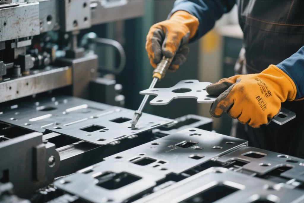
- Labor Cost: Setup time, operation monitoring, inspection, packaging.
- Secondary Operations: Costs associated with finishing, welding, assembly, heat treating, etc.
- Quality Control: Inspection time and equipment costs.
- Overhead & Profit: Supplier\’s operational costs and profit margin.
Total Cost of Ownership (TCO) Analysis
Look beyond the per-part price: – Tooling Lifetime: Factor in maintenance and potential replacement costs.
- Quality Costs: Include costs of rejects, rework, potential field failures, and warranty claims.
- Inventory Costs: Holding costs for raw materials and finished goods.
- Logistics Costs: Transportation, duties, and tariffs.
- Supplier Management Costs: Time spent managing the relationship and resolving issues.
Cost Reduction Strategies
- Design Optimization: Simplify geometry, loosen non-critical tolerances, standardize features, design for efficient material nesting.
- Material Selection: Explore alternative materials or tempers that meet requirements at lower cost.
- Process Selection: Ensure the most cost-effective stamping process is used for the required volume and complexity.
- Volume Consolidation: Increase order quantities to leverage economies of scale and reduce setup costs per part.
- Supplier Collaboration: Work with suppliers early in the design phase to identify cost-saving opportunities.
- Eliminate Secondary Ops: Design parts to be net-shape or incorporate features (like in-die tapping) to avoid post-stamping operations.
VI. Supplier Evaluation and Selection
Choosing the right partner is as important as the design itself. ### Qualification Criteria Development
- Technical Fit: Does the supplier have the right equipment, process expertise, and experience with similar parts and materials?
- Quality Systems: Do they hold necessary certifications (ISO 9001, industry-specific)? Is their QMS robust and well-documented?
- Capacity & Lead Time: Can they meet your volume requirements and delivery timelines?
- Engineering Support: Do they offer strong DFM feedback and collaborative problem-solving?
- Financial Stability: Are they financially healthy and likely to be a reliable long-term partner?
- Location & Logistics: Consider proximity, shipping costs, and supply chain risk.
- Reputation & References: Check industry reputation and ask for customer references.
Supplier Audit Methodology
- Documentation Review: Assess QMS documentation, certifications, training records, calibration logs.
- On-Site Audit (Recommended): Tour the facility, observe processes, inspect equipment condition and maintenance practices, review quality control procedures, interview key personnel.
- Key Areas: Tool room capabilities, press maintenance, process controls, inspection lab, material handling, operator training, continuous improvement initiatives.
- Remote Audits: Possible for initial screening or follow-ups, but less comprehensive.
Partnership Development Strategies
- Clear Communication: Establish regular communication channels and clear points of contact.
- Performance Metrics: Define key performance indicators (KPIs) for quality, delivery, and responsiveness. Conduct regular performance reviews.
- Collaboration: Foster a collaborative relationship, involving the supplier early in new product development.
- Continuous Improvement: Encourage and participate in joint continuous improvement initiatives.
- Long-Term Agreements: Consider longer-term contracts for critical parts to ensure supply stability and potentially better pricing.
VII. Quality Assurance for Metal Stamping Parts
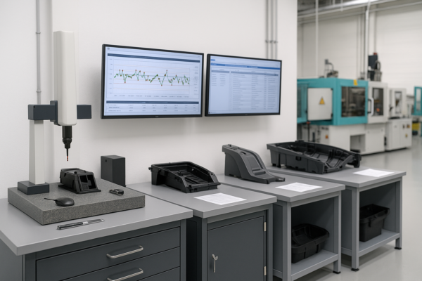
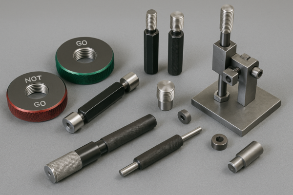
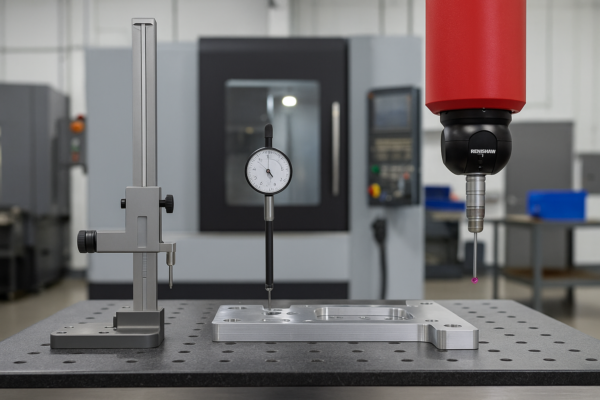
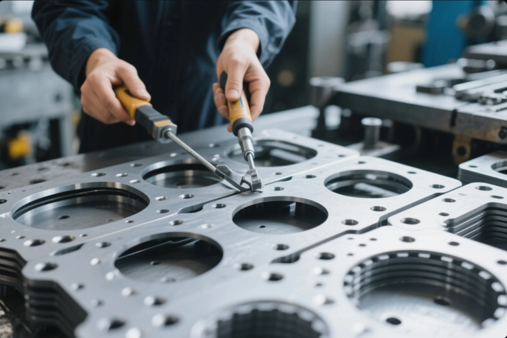
Ensuring consistent quality requires a systematic approach. ### Inspection Methods and Technologies
- Manual Inspection: Calipers, micrometers, height gauges, pin gauges for basic dimensional checks.
- Optical Comparators: 2D projection for profile checks.
- CMMs (Coordinate Measuring Machines): Accurate 3D measurement of complex geometries.
- Vision Systems: Automated 2D/3D inspection for high-volume production, checking dimensions, feature presence, and surface defects.
- Laser Scanners: Non-contact 3D scanning for complex shapes and surface analysis.
- Material Testing: Hardness testing, tensile testing (if required).
- Surface Finish Measurement: Profilometers.
Documentation Requirements
- Material Certifications: Traceable certs verifying material composition and properties.
- Process Control Plans: Document outlining how the process is monitored and controlled.
- Inspection Reports: FAI reports, in-process inspection records, final inspection reports.
- SPC Data: Control charts demonstrating process stability.
- Calibration Records: Proof that measurement equipment is accurate.
- Certificates of Conformance (CofC): Supplier statement confirming parts meet specifications.
Problem Resolution Framework
- Non-Conformance Reporting (NCR): Formal process for documenting and communicating quality issues.
- Containment: Immediate action to isolate suspect parts.
- Root Cause Analysis: Utilizing tools like 5 Whys, Fishbone Diagrams, or 8D methodology to identify the fundamental cause of the problem.
- Corrective Action: Implementing changes to tooling, process, or controls to prevent recurrence.
- Preventive Action: Proactively identifying and addressing potential future issues.
- Verification: Confirming the effectiveness of corrective actions.
VIII. Case Studies: Successful Metal Stamping Projects
(These case studies illustrate the application of principles discussed.)### Automotive Application: High-Strength Steel Bracket
- Challenge: Design a lightweight yet strong mounting bracket for a new EV platform, requiring complex forming of UHSS material with tight positional tolerances for robotic assembly.
- Solution: Early supplier collaboration led to DFM changes, optimizing bend radii and feature placement for UHSS formability. Advanced FEA simulation predicted springback accurately. A progressive die with integrated sensors was developed.
- Outcome: Successful high-volume production achieved with 60% weight reduction compared to the previous steel design. Cpk > 1.33 maintained on critical dimensions. Reduced assembly issues due to improved consistency.
Medical Device Component: Surgical Instrument Handle
- Challenge: Produce a complex, ergonomically shaped handle from 316L stainless steel, requiring deep drawing, forming, and a smooth, burr-free finish for cleanability and biocompatibility.
- Solution: Multi-stage deep drawing process combined with secondary forming operations. Specialized tooling design and polishing techniques were used. Stringent cleaning and passivation processes implemented post-stamping.
- Outcome: Parts met all dimensional, functional, and biocompatibility requirements. Eliminated need for costly machining from solid stock. Passed rigorous FDA validation.
Consumer Electronics Application: EMI Shield
- Challenge: Mass-produce a thin-gauge (0.1mm) tin-plated steel EMI shield with intricate details and tight flatness requirements for a smartphone, at extremely low cost.
- Solution: High-speed progressive die stamping (1000+ SPM) with specialized tooling for thin materials. In-die flatness control features were incorporated. Automated vision inspection ensured 100% compliance.
- Outcome: Production rates exceeded 1 million parts per week. Costs met aggressive targets. Flatness requirements achieved, preventing assembly issues.
IX. Future Trends Affecting Metal Stamping Procurement
Stay ahead by understanding emerging trends: – Digital Manufacturing Integration: Increased use of online quoting platforms, cloud-based collaboration tools, and real-time production monitoring accessible to buyers.
- Sustainability & Traceability: Growing demand for suppliers with strong environmental credentials (ISO 14001), carbon footprint data, and transparent material traceability (conflict minerals, recycled content).
- Supply Chain Resilience: Increased focus on regional sourcing, dual sourcing strategies, and supplier risk assessment tools to mitigate disruptions.
- Advanced Material Adoption: Need for suppliers capable of handling new high-strength alloys, composites, and materials for electrification and specialized applications.
- Additive Manufacturing Integration: Using 3D printing for rapid prototyping, bridge tooling, or even complex die components, complementing traditional stamping.
X. Comprehensive FAQ Section
(This section would contain 25+ detailed Q&A pairs covering common buyer questions. Examples below)1. Q: What is the typical lead time for metal stamping tooling?**A:** Highly variable based on complexity. Simple dies: 4-8 weeks. Complex progressive/transfer dies: 12-24+ weeks. Simulation and experienced toolmakers can shorten this.
- Q: How much does metal stamping tooling cost?**A:** Ranges from a few thousand dollars for simple short-run tools to hundreds of thousands (or even >$1M) for large, complex, high-volume progressive or transfer dies.
- Q: Can I get prototypes made before committing to production tooling?**A:** Yes. Options include short-run stamping, laser cutting + forming, CNC machining, or 3D printing, depending on requirements and budget.
- Q: What information is most critical for getting an accurate quote?**A:** Complete drawings with tolerances, 3D CAD models, material specification, annual volume estimate, quality requirements (PPAP/FAI), and packaging needs.
- Q: Who typically owns the stamping tooling?**A:** Often the customer pays for and owns the tool, although this is negotiable. Supplier ownership may occur but gives the customer less flexibility.
- Q: What is springback and how is it managed?**A:** The elastic recovery of metal after forming. It\’s managed through design (over-bending), material selection, and die compensation based on simulation and experience.
- Q: What are common secondary operations for stamped parts?**A:** Deburring, tapping, welding, riveting, plating, painting, heat treating, assembly.
- Q: How does material thickness affect stamping?**A:** Influences minimum bend radii, hole sizes, required press tonnage, die clearances, and potential for distortion. Thicker materials require more robust tooling and higher forces.
- Q: What is the difference between blanking and piercing?**A:** Blanking cuts the outer profile of the part from the sheet (the piece cut out is the part). Piercing punches holes or shapes within the part (the piece punched out is scrap).
- Q: How important is material grain direction?**A:** Very important, especially for bending harder materials. Bending parallel to the grain increases the risk of cracking. Design parts to be bent across the grain where possible.
(…continue with 15+ more detailed Q&A pairs covering topics like tolerances, specific processes, quality standards, cost estimation, supplier audits, etc.)
XI. Resources and Tools
- Downloadable Templates:
- [Link Placeholder] Comprehensive RFQ Template for Metal Stamping
- [Link Placeholder] Supplier Evaluation Scorecard
- [Link Placeholder] Stamping Part Quality Checklist
- Calculation Tools (Conceptual Links):
- [Link Placeholder] Online Bend Allowance Calculator
- [Link Placeholder] Basic Material Cost Estimator Tool
- [Link Placeholder] Volume Break-Even Analysis Worksheet
- Industry Standards Reference:
- ISO 9001, IATF 16949, AS9100, ISO 13485 (Quality Management)
- ASTM Standards for material specifications (e.g., A1008 for steel sheet)
- ASME Y14.5 (GD&T)
- ANSI Z1.4 (Sampling Procedures)
XII. Conclusion
Procuring metal stamping parts effectively requires a blend of technical understanding, strategic planning, and diligent supplier management. This guide has provided a comprehensive framework covering the entire lifecycle, from design fundamentals and specification development to cost analysis, supplier selection, and quality assurance. By applying these principles, engineers and procurement professionals can avoid common pitfalls, optimize costs, ensure part quality, and build strong, reliable partnerships with their metal stamping suppliers. Remember that early collaboration with knowledgeable suppliers during the design phase is often the most impactful step towards achieving success in your metal stamping projects.