OEM Metal Casting Parts: What Engineers Must Know Before Ordering
Ordering OEM metal casting parts without technical understanding leads to tolerance errors, delayed lead times, and failed inspection reports.
This ultimate guide for engineers covers every critical step in OEM casting—from CAD drawing preparation and tolerance management to standards, post-processing, and real-world examples.
Based on global standards like ISO, ASTM, and ASME, and informed by industry leaders such as AFS, this resource ensures you never miss a requirement in your next RFQ or production run.
Why Accurate Engineering Preparation Matters in OEM Casting
In OEM metal casting, even a minor oversight in geometry, tolerance assignment, or material choice can cause:
- Tooling rework delays (2–4 weeks)
- Increased scrap rates due to poor gating
- Excessive machining cost from misaligned shrinkage estimates
- Part rejection due to surface finish mismatches
An engineer’s job isn’t just to send a model—it’s to define a castable, inspectable, and machinable part that meets function, cost, and certification goals.
Key OEM Casting Processes You Should Know
Casting is not one-size-fits-all. Understanding process basics helps you align designs with the right manufacturing route.
| Process | Best For | Notes |
|---|---|---|
| Sand Casting | Large parts, low-medium volume | Flexible, cost-effective, coarse finish |
| Investment Casting | Complex geometry, tight tolerance | High accuracy, better surface, great for stainless steels |
| Die Casting | High-volume, non-ferrous alloys | Best for aluminum, zinc, magnesium. Precise but tooling-intensive |
| Shell Molding | Thin walls, medium detail | Excellent dimensional accuracy for steel and iron |
| Gravity Casting | Simpler tooling, medium volumes | Used for aluminum and brass parts with consistent section thickness |
For in-depth comparisons, consult:
Preparing Accurate 2D/3D Drawings for Cast Parts
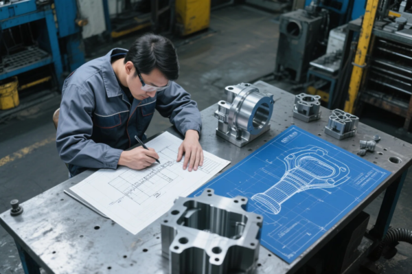
Why Drawings Still Matter in the 3D CAD Era
Even in model-based engineering, 2D drawings remain essential. That’s because casting foundries rely on:
- Dimensional tolerances
- Surface finish symbols
- Machining instructions
- Critical-to-function (CTF) features
- Shrinkage annotations
These details are rarely embedded in a 3D STEP file alone. Submitting incomplete or vague files causes toolmakers to guess—and that’s where errors begin.
Accepted CAD Formats and Standards
- 3D files: STEP (.stp), IGES (.igs), [Parasolid (.x_t)]
- 2D drawings: PDF format referencing ASME Y14.5 or ISO 129-1 for dimensioning
What to Include in Your Drawings
| Element | Why It’s Required |
|---|---|
| Material name and standard | E.g., ASTM A356-T6 aluminum or EN-GJS-400-15 ductile iron |
| Shrinkage % | Usually 1–2.5%, depends on alloy and process |
| Draft angles | 0.5° for die cast; 1–3° for sand or investment castings |
| Tolerance bands | Follow ISO 8062-3 or IT grades per Engineering Toolbox |
| Machined surfaces marked | Must be labeled with finish symbols like Ra 3.2 or “machine this face” |
| Parting lines suggested | Prevent flash and mold mismatch errors |
| Gating/runner suggestions | Optional, helps with directional solidification |
Design Tip: Don’t Over-Tolerate
Over-specifying tolerances can increase costs 200–400% due to post-processing. According to Xometry’s tolerance calculator, use:
- ±0.5–1.0 mm for non-critical cast surfaces
- ±0.1–0.2 mm for machined features
- Ra 6.3–12.5 μm for painted or hidden parts
- Ra 1.6–3.2 μm for functional mating surfaces
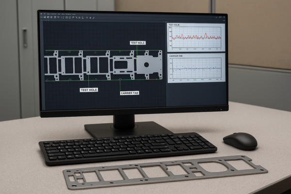
What Foundries Use Drawings For
- To determine part complexity and assign proper process (investment, sand, die)
- To create gating, riser, and core box tooling
- To simulate flow and cooling using MAGMASOFT or ESI ProCAST
- To identify CTF zones for machining fixturing
Common Mistakes in OEM Casting Drawings
- Missing shrinkage factors → leads to undersized or warped parts
- Ambiguous tolerances → causes interpretation disputes
- Ignoring parting lines → leads to flash and core shift
- Assuming 3D file is “enough” → omits critical inspection notes
Always collaborate with your foundry’s engineering team before freezing the design. Suppliers like Prime offer free Design for Casting reviews and simulation reports to optimize flow, cooling, and finish from the start.
Tolerances and Surface Finishes for OEM Castings

Why Tolerances Directly Affect Cost and Inspection Outcomes
OEM engineers often underestimate how tolerances drive tooling complexity, machining time, and rejection risk.
A casting tolerance of ±0.3 mm vs. ±1.0 mm may sound minor—but it could mean:
- CNC post-processing vs. as-cast delivery
- \$2 part vs. \$7 part
- 30% vs. 90% first-pass yield
According to ISO 8062-3 and VDG P690, tolerance grades vary by casting method.
Tolerance Chart by Process
| Casting Type | Linear Tolerance (mm) | Best Application |
|---|---|---|
| Sand Casting | ±0.8–3.0 mm | Large parts, rough finishes |
| Investment Casting | ±0.3–1.5 mm | Aerospace, medical, tight-profile designs |
| Die Casting | ±0.1–0.5 mm | High-volume aluminum/zinc parts |
| Shell Molding | ±0.3–0.8 mm | Complex steel/iron parts |
Source: MetalTek Guide and AFS Handbook
Surface Finish Standards Explained
Surface finish (Ra, µm) indicates smoothness of a part’s surface. It affects:
- Aesthetics
- Corrosion resistance
- Mating/sealing performance
- Paint and coating adhesion
| Process | Typical Ra Value (µm) | Comments |
|---|---|---|
| Sand Casting | 12.5–25 | Rough, visible grain, requires smoothing |
| Investment Casting | 1.6–6.3 | Fine, near-machined surface |
| Die Casting | 0.8–3.2 | Excellent for visible aluminum housings |
| CNC Machining | 0.4–1.6 | Precision surfaces, sealing faces |
Refer to ASME B46.1 and Finishing.com Roughness Chart for conversion tables and visuals.
When to Choose Post-Casting Surface Treatments
Post-treatments enhance durability and appearance, especially for demanding environments.
- Shot blasting – cleans scale, improves paint adhesion
- Vibratory tumbling – deburring and smoothing small parts
- Anodizing – great for aluminum, improves corrosion and cosmetic appeal
- Powder coating – uniform finish, good impact resistance
- Polishing or buffing – cosmetic stainless steel or decorative trim
See Lincolnelectric Finishing Guide and Able Electropolishing for examples by material and finish spec.
Real-World Case Study: Precision Investment Cast Valve Body for European Pump OEM
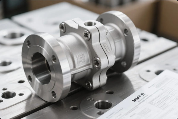
Project Summary
- Client: German fluid control OEM
- Component: 3” Stainless Steel Valve Body
- Industry: Industrial water pumps
- Casting Method: Investment casting
- Annual Volume: 2,500 pcs/year
- Material: ASTM A351 CF8M (316 stainless equivalent)
- Certifications Required: ISO 9001, EN 10204-3.1, RoHS
Initial Challenges
The OEM had been sourcing the part locally in Europe at high cost, with inconsistent lead times. Their pain points included:
- Long RFQ cycles (2+ weeks for a quote)
- Warped valve seats due to uncontrolled cooling
- High scrap rates in CNC finishing (flatness errors >0.1 mm)
- No MTRs or casting simulation documentation
They approached Prime seeking a cost-competitive supplier with reliable QA processes and traceability.
Prime’s Engineering Solution
Our engineering team requested their STEP model + 2D PDF drawing and performed a DFM review. Key actions included:
- Updated gating layout using MAGMASOFT to reduce thermal distortion
- Added chill zone near flange to prevent sink defects
- Built wax tooling and ceramic shell molds with ±0.3 mm casting tolerance
- Applied shot blasting + CNC face milling for sealing surfaces (Ra <1.6 μm)
-
Delivered full documentation:
- Material Test Report (EN 10204-3.1)
- Dimensional Report (CMM)
- Visual inspection photos
- NDT (dye penetrant)
Outcome & Client Feedback
- Unit cost reduced by 28% compared to European source
- Delivery time cut from 11 weeks to 4.5 weeks
- Flatness of flange within 0.05 mm, eliminating sealing failures
- Client expanded order to include 4” and 6” sizes in same family
“Prime solved a problem our local supplier couldn’t for years. Their engineering support during tooling design saved us from another failed season.”
— Head of Procurement, German OEM
Certifications That Matter in OEM Casting Projects
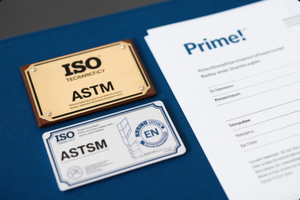
Why Certifications Define OEM Approval
In OEM manufacturing, compliance is non-negotiable. Whether for safety-critical parts in aerospace or emission-certified components in automotive, castings must meet:
- Dimensional accuracy
- Mechanical properties (tensile, yield, elongation)
- Traceable origin and test reports
- Global, regional, or client-specific regulations
Without the right certificates, your shipment risks being rejected—even if the parts look perfect.
Key Quality Management Standards
| Certification | Applies To | Issued By |
|---|---|---|
| ISO 9001 | General quality system | ISO |
| IATF 16949 | Automotive suppliers | IATF |
| AS9100 | Aerospace part production | SAE |
| ISO 13485 | Medical devices & implants | ISO |
| ISO 14001 | Environmental management | ISO |
Prime is fully certified to ISO 9001 and has pre-compliance support for IATF projects through partnered audit labs.
Material and Foundry Standards
| Standard | Type | Example Use Case |
|---|---|---|
| ASTM A27 | Carbon steel castings | Brackets, housings |
| ASTM A536 | Ductile iron | Pump casings, bearing supports |
| ASTM B26 | Aluminum alloys | Engine mounts, brackets |
| EN 1561 | Grey iron | Hydraulic components, engine blocks |
| ISO 4991 | General cast steel | Global OEM acceptance |
| DIN 1690 | German casting quality | Common in EU-based RFQs |
See full listings via ASTM Castings Directory and CEN EN Standards.
Material Test Reports and Certification Packages
Prime provides the following by default (unless waived by client):
- EN 10204-3.1 MTR (includes chemical & mechanical data)
- Dimensional reports (CMM or inspection table)
- Certificate of conformance (COC)
- Optional: PPAP, FAI, and traceability matrix by heat lot or melt ID
Inspection is performed internally and by third-party labs such as SGS, TÜV Rheinland, or Bureau Veritas.
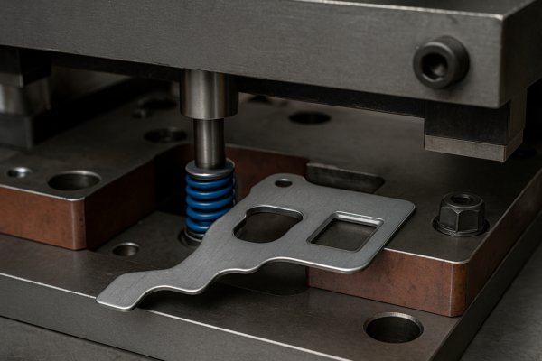
The Role of Secondary Machining in Casting Precision
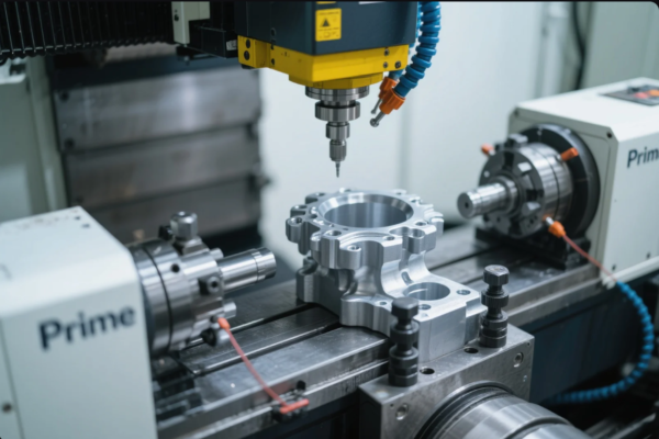
Why Most OEM Castings Still Require Machining
Although some parts can be delivered as-cast, most OEM applications involve at least one critical surface that demands machining.
Common features needing post-casting precision include:
- Shaft bores
- Threaded holes (tapped or drilled)
- Sealing flanges
- Bearing fits or gear seats
- Mounting patterns with tight location tolerances
Without secondary machining, these surfaces may:
- Fail assembly fit checks
- Leak under pressure
- Exceed flatness or runout specs
Typical OEM Machining Operations After Casting
| Operation | Tolerance Achievable | Application Examples |
|---|---|---|
| CNC milling | ±0.01 mm | Flat mounting faces, flanges |
| Boring | ±0.005 mm | Shaft holes, bushings |
| Tapping/threading | ISO metric/UNC-UNF | Brackets, fluid connectors |
| Broaching/keyways | ±0.02 mm | Pulley and gear hubs |
Tooling is selected based on part volume and geometry. Prime uses CNC centers from DMG Mori, tool presetters from Zoller, and inspection from Mitutoyo and Keyence.
Machining Allowance in Casting Design
You must account for machining allowance during the design phase. This is the extra material left on features that will be finished post-casting.
Typical allowances:
- 1.5–3 mm for rough CNC areas (cast surface variation)
- 0.5–1 mm for die-cast surfaces (less variation)
- Defined by ISO 8062-3 or supplier-specific standards
Don’t forget to mark all machined faces clearly in the 2D drawing. Ambiguity causes over-processing, waste, or rejected parts.
Hybrid Manufacturing: Casting + Machining Integration
Some projects are better served by integrating machining and casting from the start. Advantages include:
- Lower raw material waste (vs. full bar stock)
- Reduced setup time
- Seamless GD\&T coordination
- Unified traceability
Prime supports hybrid workflows where our foundry and machining teams collaborate from DFM to final QA. This reduces lead time by 20–40% and total cost by up to 35% vs. outsourcing machining separately.
Frequently Asked Questions: 10 Things Engineers Ask Before Ordering OEM Castings

1. Do I need to submit both 2D and 3D files?
Yes. While 3D models (STEP, IGES) help with tooling design, only 2D drawings contain critical info like tolerances, surface finish, machining zones, and parting lines. Refer to ASME Y14.5 and ISO 129-1 for standards.
2. Can I request surface finishes like anodizing or powder coating?
Yes. Prime offers full post-processing, including anodizing for aluminum, powder coating, and electropolishing for stainless steel.
3. What’s the difference between IT grades in ISO 8062?
IT (International Tolerance) grades define allowable variation in cast parts. Lower numbers = tighter tolerances.
- Sand casting: IT13–16
- Die casting: IT8–11
- Investment casting: IT6–10
See the ISO 8062-3 standard for full tables.
4. How does material shrinkage affect my design?
Each alloy shrinks during cooling. For example:
- Aluminum: \~1.3%
- Gray iron: \~1.0%
- Stainless steel: \~2.0%
Always confirm shrinkage values with your foundry. See Matmatch Material Properties.
5. How fast can Prime deliver samples?
Typical lead time:
- Sand casting: 15–20 days
- Die casting: 20–30 days
- Investment casting: 25–35 days
Urgent tooling projects are supported via express programs. View our process overview.
6. What inspection reports do you provide?
We supply:
- MTRs per EN 10204-3.1
- Dimensional reports (CMM, hand tools)
- Visual inspection sheets
- Optional: NDT (X-ray, dye penetrant), PPAP, FAI
7. Do you support mixed-process parts (cast + CNC + weld)?
Yes. We deliver turnkey assemblies that include:
- Castings
- Machining
- Surface treatment
- Welding
- Assembly & packaging
Ideal for BOM consolidation and cost control.
8. What’s the minimum order quantity?
Standard MOQ is 100 pcs. However, we support:
- Prototypes (1–10 pcs) in resin, sand, or CNC billet
- Pilot runs (50–200 pcs) for validation
Custom tooling amortization can be built into unit pricing.
9. Can I get a price estimate without drawings?
We can quote approximate pricing if you provide:
- Reference image or similar part photo
- Basic dimensions + weight
- Target quantity
- Material type (e.g., A356, SS304)
For accurate quotes, we recommend uploading drawings via Prime’s inquiry page.
10. Which casting method is best for high precision + medium volume?
In most cases:
- Investment casting for complex geometry, tight tolerance
- Die casting for aluminum/zinc in volume (>10k/year)
- Shell molding for iron/steel up to IT9 with clean finish
Use this AFS Casting Process Selector Tool to compare processes by geometry, volume, and budget.
Conclusion: Ready to Optimize Your OEM Casting Project?

Choosing the right casting supplier isn’t just about price—it’s about consistency, documentation, communication, and technical support.
At Prime, we’ve helped OEMs in over 25 countries successfully scale from prototype to full production using:
- ISO-certified processes
- In-house simulation tools (MAGMASOFT, SolidWorks)
- 10 dedicated casting and CNC production lines
- Rapid prototyping options with sand and investment tooling
- Strict adherence to ISO 9001, ASTM standards, and customer-specific specs
Whether you need 100 pump housings or 50,000 die-cast enclosures, we tailor each program to your product’s requirements and budget.
Let’s Get Started
📩 Email us directly: [email protected]
🌐 Visit: https://primecustomparts.com
📎 Upload your CAD files: Contact Page Upload Tool
📍 Serving: North America, Europe, Middle East, Australia, and global sourcing markets
You’ll receive:
- A free DFM design review
- Technical consultation on casting method + material
- Rapid quote with clear timeline, unit cost, tooling structure
- Sample lead time forecast
Stop reworking cast parts. Start getting them right from the mold.
Backed by over 20 years of casting expertise, Prime delivers precision parts—on time, on spec, and ready for inspection.