What Does CNC Really Mean in Modern Cutting Technology?
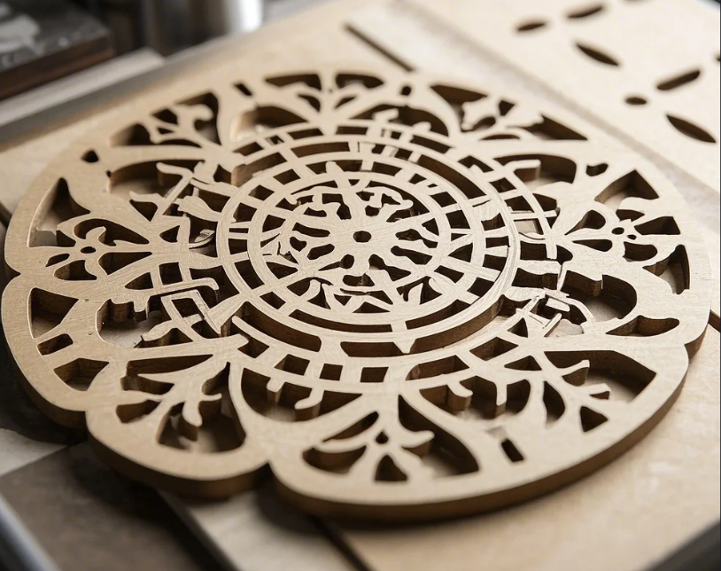
After running CNC operations since 1998, we’ve seen how Computer Numerical Control revolutionized cutting – achieving tolerances impossible with manual methods while boosting productivity 300-500%.
CNC cutting means: 1) Computer-guided tool paths 2) Pre-programmed dimensions (typically within ±0.005") 3) Automated material removal 4) Repeatable processes – using coded G&M instructions that direct cutting tools along X/Y/Z axes at controlled speeds (RPM) and feed rates (IPM).
Let’s breakdown how this transforms material processing…
How Do CNC Machines Interpret Cutting Commands?
The digital brain behind physical cuts.
Every CNC cut follows this workflow: 1) CAD design → 2) CAM programming → 3) G-code generation → 4) Machine execution – where G01 means linear cut, G02/G03 indicate arcs, and M03 starts spindle rotation, with positioning accuracy to 0.0002" on premium machines.
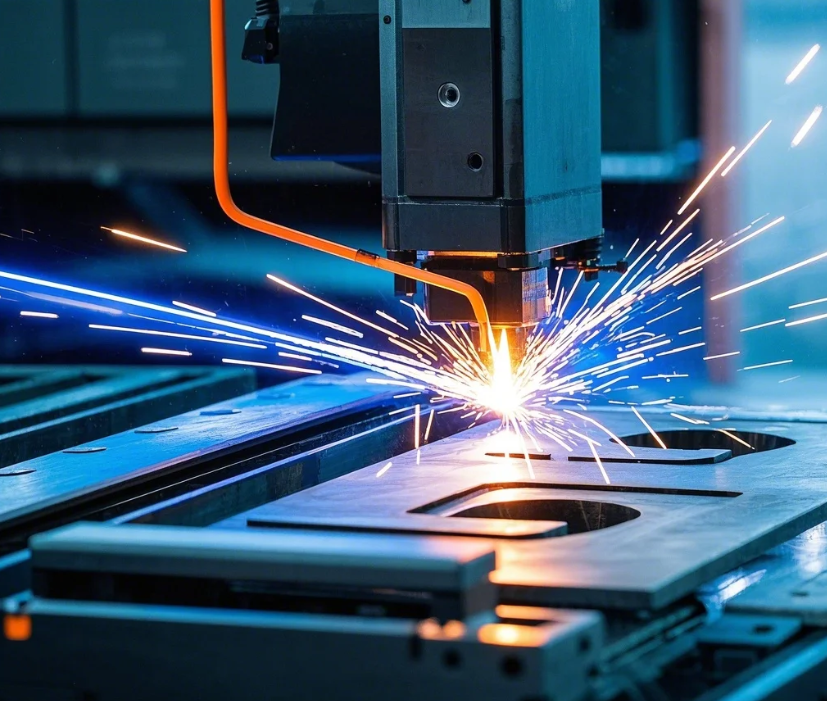
Common CNC G-Codes for Cutting
| Code | Function | Parameter Example |
|---|---|---|
| G00 | Rapid positioning | X10.5 Y3.2 (move to coordinates) |
| G01 | Linear cut | X5.0 F20.0 (feed rate in inches/min) |
| G02 | Clockwise arc | X3.0 Y2.0 I1.5 J0.5 (arc center offsets) |
| G03 | Counter-clockwise arc | Same format as G02 |
| G90 | Absolute positioning | Uses machine coordinates |
Motion Control Parameters
| Variable | Typical Range | Impact on Cut Quality |
|---|---|---|
| Spindle Speed | 500-15,000 RPM | Surface finish |
| Feed Rate | 5-500 IPM | Tool life |
| Depth of Cut | 0.005-0.5" | Vibration levels |
| Stepover | 10-50% tool diameter | Machining time |
Key Cutting Applications:
- Profile cutting (outside contours)
- Pocketing (internal material removal)
- Drilling (hole patterns)
- Engraving (surface details)
What Materials Can CNC Cutting Machines Process?
From aluminum to zirconium alloys.
Our CNC routers/mills regularly cut: 1) Metals (aluminum, steel, titanium) 2) Plastics (ABS, PTFE, polycarbonate) 3) Composites (CFRP, G10) 4) Wood products – using specialized tools like carbide end mills for metals (up to 65 HRC) and diamond-coated bits for carbon fiber.
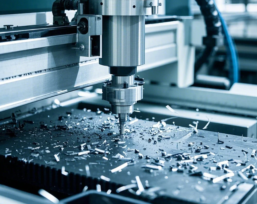
Material-Specific Cutting Parameters
| Material | Recommended Tool | Speed (SFM) | Chip Load |
|---|---|---|---|
| 6061 Aluminum | 3-flute carbide | 800-1,200 | 0.003-0.010" |
| Mild Steel | Coated end mill | 300-600 | 0.002-0.006" |
| Titanium | 6-flute variable helix | 150-250 | 0.001-0.003" |
| ABS Plastic | 2-flute upcut | 600-900 | 0.008-0.015" |
Tool Wear Indicators
| Symptom | Probable Cause | Solution |
|---|---|---|
| Edge chipping | Excessive feed rate | Reduce IPM 20% |
| Flank wear | Hard material | Switch to ceramic tool |
| Built-up edge | Low SFM | Increase RPM |
| Breakage | Deflection | Reduce DOC |
Common Material Challenges:
- Aluminum (gumminess)
- Stainless (work hardening)
- Plastics (melting)
- Composites (delamination)
How Does CNC Cutting Accuracy Compare to Manual Methods?
Precision measured in microns.
CNC cutting achieves: 1) Repeatability within 0.0005" 2) Angular accuracy <0.01° 3) Surface finishes to 8μin Ra – versus manual tolerances typically ±0.015" due to human variables like hand tremors and measurement errors.
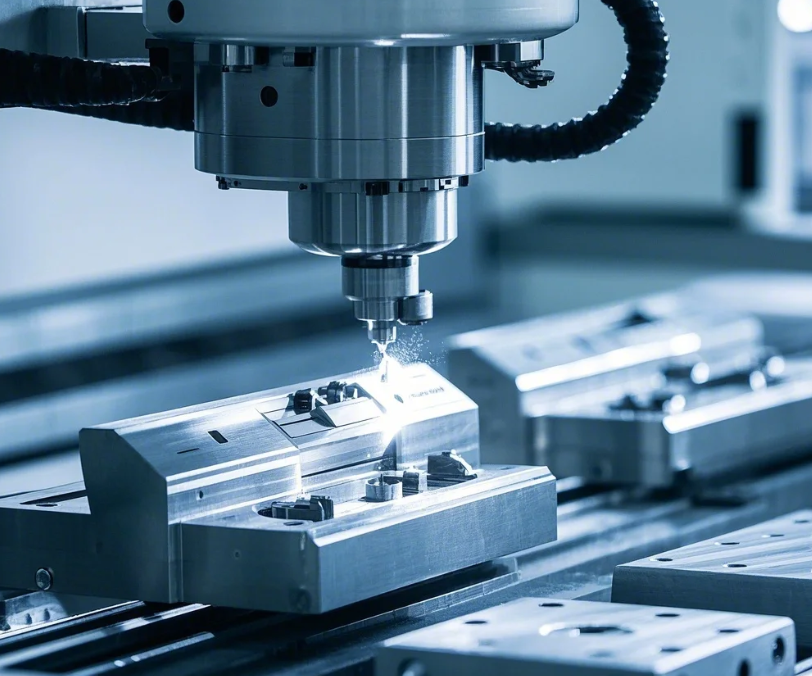
Accuracy Benchmark Testing
| Measurement | Manual Machining | Standard CNC | High-Precision CNC |
|---|---|---|---|
| Linear | ±0.015" | ±0.005" | ±0.0002" |
| Circularity | 0.010" TIR | 0.002" TIR | 0.0005" TIR |
| Flatness | 0.005"/ft | 0.001"/ft | 0.0002"/ft |
| Angle | ±0.5° | ±0.1° | ±0.01° |
Cost-Benefit Analysis
| Factor | CNC Advantage | Cost Premium |
|---|---|---|
| Setup time | 70% faster | 2-3x equipment cost |
| Scrap rate | 90% reduction | Higher maintenance |
| Labor needs | 1 operator: 3 machines | Training investment |
| Job changeover | <5 minutes | CAM software costs |
Critical Quality Applications:
- Medical implants
- Aerospace components
- Optical mounts
- Injection molds
What Are the Main Types of CNC Cutting Processes?
Subtractive manufacturing’s toolkit.
We utilize these 5 cutting methods daily: 1) Milling (multi-axis material removal) 2) Turning (rotational parts) 3) Laser (non-contact cutting) 4) Waterjet (cold cutting) 5) Plasma (conductive metals) – each suited for specific materials and feature requirements from thin slots (<0.5mm) to heavy plate (>100mm).
Process Selection Matrix
| Method | Best Materials | Thickness Range | Tolerance |
|---|---|---|---|
| CNC Milling | Metals, plastics | 0.1-12" | ±0.005" |
| CNC Turning | Round parts | 0.1-24" dia | ±0.001" |
| Laser | Thin metals | 0.02-0.5" | ±0.004" |
| Waterjet | Any material | 0.1-10" | ±0.006" |
| Plasma | Conductive | 0.5-2" | ±0.030" |
Cut Quality Comparison
| Process | Kerf Width | Heat Affected Zone | Edge Angle |
|---|---|---|---|
| Milling | Tool diameter | Minimal | 90° |
| Laser | 0.004-0.020" | Medium | 5-10° taper |
| Waterjet | 0.030-0.050" | None | 1-3° taper |
| Plasma | 0.060-0.120" | Large | 3-8° taper |
Industry-Specific Preferences:
- Automotive (milling/turning)
- Signage (laser)
- Aerospace (waterjet)
- Structural steel (plasma)
Conclusion
CNC cutting transforms digital designs into physical parts with unmatched precision and repeatability across virtually all engineering materials using programmed tool movements measured in thousandths of an inch.

