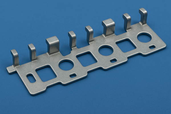
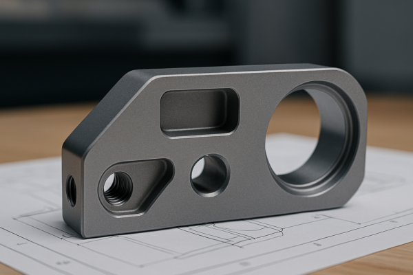
How to Stamp Metal Parts? The Complete Guide for Precision Fabrication

Metal stamping transforms flat stock into complex shapes with up to ±0.025mm accuracy at 300+ strokes per minute. Poor setup causes 70% of dimensional defects in formed parts.
Snippet paragraph: To stamp metal, first choose a press (mechanical for speed, hydraulic for force), design matched punch/die sets with proper clearance (10-15% material thickness), then feed coil stock through the tooling – typical tolerances reach IT8-IT10 for production runs.
Proper lubrication is essential – 85% of tool failures stem from galling.
How to Select the Right Metal Stamping Press?
Press choice balances speed, force, and precision needs.
Snippet paragraph: For thin materials (<3mm), use mechanical presses (200-1,200 SPM) up to 400 tons; for thick plates (3-10mm), employ hydraulic presses (10-200 SPM) producing 2,000+ tons – servo-electric models now offer 0.01mm repeatability for delicate electronics.

Stamping Press Specifications
| Parameter | Mechanical Press | Hydraulic Press | Servo Press |
|---|---|---|---|
| Speed (SPM) | 200-1,200 | 10-200 | 20-500 |
| Force Range | 20-400 tons | 50-5,000 tons | 5-600 tons |
| Accuracy | ±0.05mm | ±0.1mm | ±0.01mm |
| Energy Use | 30-50kW | 50-200kW | 15-40kW |
| Best For | High-volume thin sheets | Heavy/thick materials | Precision forming |
Case Study: Automotive panels use 800-ton mechanical presses at 45 strokes/min for 1.5mm steel.
What Clearance Should You Use for Punches and Dies?
Material thickness determines the critical gap.
Snippet paragraph: Set punch-to-die clearance at 7-15% of material thickness (10% for steel, 12% aluminum, 8% brass). Insufficient clearance increases burrs by 300%, while excessive gaps cause rollover defects in cut edges.
Recommended Clearances (Per Side)
| Material | Thickness (mm) | Clearance (%) | Actual Gap (mm) |
|---|---|---|---|
| Mild Steel | 1.0 | 10 | 0.10 |
| Aluminum 5052 | 2.0 | 12 | 0.24 |
| Brass C260 | 0.8 | 8 | 0.064 |
| Stainless 304 | 1.5 | 15 | 0.225 |
Pro Tip: For progressive dies, add 0.005mm clearance per additional station.
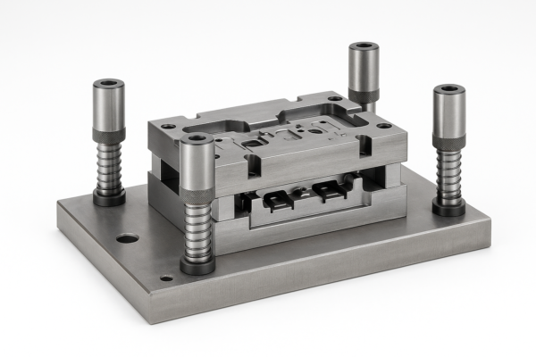
How to Design Stamping Dies?
Die engineering combines metal flow theory with practical constraints.
Snippet paragraph: Design die blocks from D2 tool steel (HRC 58-62) with corner radii of 2-3x material thickness. Include stripper plates applying 20-30% of punch force, and allow 0.1-0.3mm draft angles on formed features to ease part ejection.
Critical Die Design Ratios
| Feature | Design Rule | Example (1mm steel) |
|---|---|---|
| Punch edge radius | 5-10% of thickness | 0.05-0.10mm |
| Emboss height | ≤40% of thickness | 0.4mm max |
| Hole-to-edge distance | 1.5x thickness | 1.5mm minimum |
| Bend relief width | ≥ thickness | 1.0mm |
Red Flag: Avoid acute angles below 30° in die geometry – they concentrate stress and reduce tool life by 70%.
What Lubrication System Works Best?
The right lubricant prevents galling and reduces wear.
Snippet paragraph: Apply chlorinated oils (20-30g/m²) for steel stamping, water-soluble polymers for aluminum, and PTFE-based films for stainless steel – lubricity must balance with easy post-stamp cleaning using alkaline washes at 60-80°C.
Lubricant Performance Comparison
| Type | Friction Coefficient | Operating Temp | Corrosion Risk |
|---|---|---|---|
| Chlorinated oil | 0.05-0.08 | 20-150°C | Medium |
| Synthetic ester | 0.07-0.10 | 0-200°C | Low |
| Water-based | 0.10-0.15 | 5-80°C | Very low |
| Dry film (PTFE) | 0.02-0.05 | -20-260°C | None |
Warning: Lubricant viscosity should be 20-60 cSt at operating temperature for proper film strength.
How to Set Up a Stamping Operation?
Process parameters require fine-tuning.
Snippet paragraph: Start with 70% calculated tonnage, set press speed to 30% maximum, and adjust shut height to 0.05mm above material thickness – then gradually increase parameters while monitoring part dimensional stability (±0.02mm variation indicates proper setup).
Stamping Troubleshooting Guide
| Defect | Likely Cause | Solution |
|---|---|---|
| Excessive burrs | Worn punch/die | Replace tools or sharpen edges |
| Part sticking | Insufficient draft angle | Increase to 0.5-1.0° |
| Edge cracking | Too little bend radius | Use 4-6x material thickness |
| Dimensional drift | Uneven die wear | Resharge or adjust alignment |
Data Point: Properly maintained stamping tools last 500,000-1,000,000 cycles before requiring rework.
How to Choose the Right Stripper Plate?
The stripping force must overcome material springback.
Snippet paragraph: Select spring-loaded strippers with 2-3x the material thickness travel distance, applying 20-30% of punch force (e.g. 1-ton stripper force for a 5-ton punch) – polyurethane springs offer more consistent force than coil springs over time.
Stripper Plate Configurations
| Type | Force (kgf/cm²) | Advantages |
|---|---|---|
| Fixed | 50-100 | Simple construction |
| Spring-loaded | 80-150 | Adaptive to material variations |
| Pneumatic | 100-200 | Precise control |
| Hydraulic | 150-300 | Heavy material capability |
Rule of Thumb: Stripper opening should exceed material thickness by 25% for reliable part release.
Conclusion
Precision metal stamping demands carefully calculated clearances, robust tooling design, and controlled process parameters – when executed properly, it achieves 98.5%+ material utilization rates while maintaining ±0.05mm tolerances for high-volume production.